INDEX |
||
|
|
||
STRUCTURAL FIELD WELDING & INSPECTION |
||
|
|
||
Section |
Title |
Page |
|
I |
2 |
|
|
II |
3 |
|
|
III |
8 |
|
|
IV |
8 |
|
|
V |
12 |
|
|
VI |
14 |
|
|
VII |
16 |
|
|
VIII |
26 |
|
|
IX |
29 |
|
|
X |
30 |
|
|
XI |
34 |
|
|
XII |
42 |
|
|
XIII |
42 |
|
|
XIIII |
42 |
|
|
XV |
43 |
|
|
XVI |
48 |
|
PREFACE
This IM is written to help meet a continuing and growing need among inspectors whose common interest is to function as welding inspectors in addition to their other inspection duties. These inspectors function under the direction of the Resident Construction Engineers. Despite the wide diversity in training and background of these inspectors it becomes more evident each year that continued progress is increasingly more dependent upon technical review of the specifications.
With the increased use of the new higher strength steels it is even more important than ever before that better welding inspectors are needed to understand and to enforce the specifications so that the minimum design criteria are incorporated into the final structure.
Since welding is essentially a metallurgical operation it is best that the inspector understand a few of the basic fundamentals and the technology in applying this knowledge to obtain sound weldments. The illustrated procedures, inspection methods and data presented in this manual are for the inspector’s beneficial study and to reinforce their periodic references to various welding problems.
All references are to the American Welding Society Specifications AWS D1.5 or AWS D1.1.
DESCRIPTION
Field-weld metal members shall use the shielded metal arc and flux-cored arc welding processes.
SECTION I
Opportunity & Use
This manual outlines the inspector's duties and responsibilities for the proper inspection of weldments made under field conditions by approved welding processes. It is intended as an informational source for the inspection of methods and weldments.
It is the responsibility of the engineer or the supervisor appointed by them to see that proper methods outlined in this manual are understood and applied to the respective work.
Most of the welding specifications are incorporated into this manual but the inspector may find particular instances where the plans will carry additional welding requirements, and in those cases the plans must at all times be followed.
There are at times, errors on the plans, especially on the use of welding symbols. Whenever there is reason to question a particular drawing the inspector should consult their engineer and have them verify it with the Bridges & Structures Bureau in Ames.
SECTION II
Welding Processes & Terminology
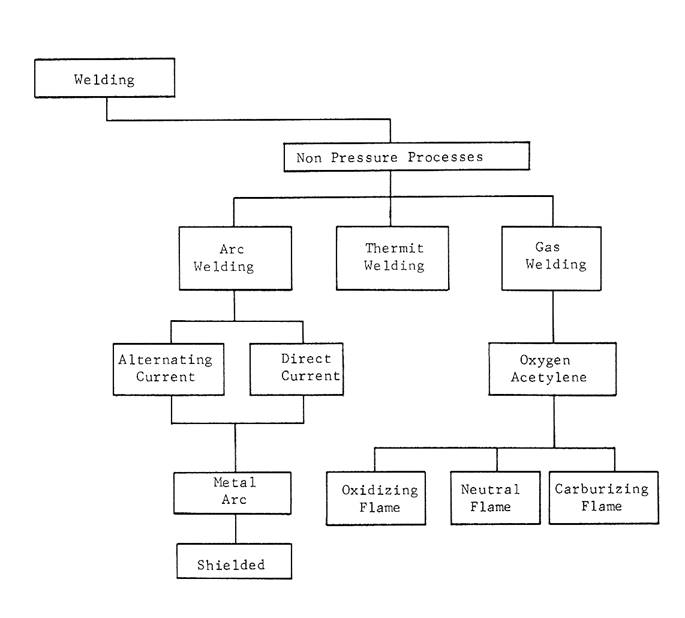
Welding is a localized coalescence of metal wherein coalescence is produced by heating to suitable temperatures, with or without the application of pressure, and with or without the application of filler metal. The filler metal either has a melting point approximately the same as the base metal or has a melting point below that of the base metal but above 800ºF.
Non-Pressure Welding
Arc welding is one of the most common and widely known forms of welding in use today. It is not surprising to find that most of our problems deal with this type of welding, both in the field and in the fabricating shop. This IM is written for the sole purpose of inspection of arc welding done on the job site.
TERMINOLOGY
Air Carbon Arc Cutting: An arc cutting process wherein the severing of metals is affected by melting with the heat of the arc and an air stream is used to facilitate the removal of the metal.
Arc Blow: The swerving of an electric arc from its normal patch because of magnetic forces.
Arc Gouging: The application of arc cutting wherein a U-groove is formed.
Automatic Welding: Welding with equipment, which performs the entire welding operation without constant observation and adjustment of the controls by an operator.
Axis of a Weld: A line drawn through the length of a weld.
Backing: Material (usually metal) backing up the joint during welding to facilitate obtaining a sound weld at the root.
Back Weld: A weld deposited at the back of a single groove weld
Bare Electrode: A filler metal electrode without a coating or covering other than that used for drawing the wire.
Base Metal: The metal to be welded or cut.
Bevel: A type of edge preparation.
Bead Weld: A type of weld composed of one or more string or weave beads deposited on an unbroken surface.
Butt Joint: A joint between two members lying approximately in the same plane.
Chamfer: The contour prepared on the edge of a member to be welded.
Crater: A depression at the termination of a weld bead.
Crater Crack: A crack in the crater of a weld bead
Depth of Fusion: The distance that fusion extends into the base metal from the surface melted during welding.
Downhand: Position of welding wherein welding is done from the top side and the axis of the weld metal is horizontal.
Electrode: (Metal Arc Welding) Filler metal in the form of a wire or rod, either bare or covered, through which current is conducted between the electrode holder and the arc.
Faying Surface: That surface of a member, which is in contact with another member to which it is to be joined.
Filler Metal: Metal to be added in making a weld.
Flux: Material used to prevent dissolve or facilitate removal of oxides and other undesirable substances.
Flux Cored Arc Welding: An arc welding process in which the consumable electrode wire is hollow and is filled with flux material. Shielding may be from the solid flux only or from solid flux along with additional gas shielding.
Gas Metal Arc Welding: An arc welding process wherein coalescence is produced by heating with an electric arc between a filler metal (consumable) electrode and the work. Shielding, is obtained from a gas, a gas mixture (which may contain an inert gas) this process has sometimes been called Mig Welding.
Gas Pocket: A weld cavity caused by entrapped gas
Heat-Affected Zone: That portion of the base metal which has not been melted, but whose mechanical properties or micro-structures have been altered by welding.
Interpass Temperature: In a multiple-pass weld, the lowest temperature of the deposited weld metal before the next pass is started.
Kerf: The space from which metal has been removed by a cutting process.
Manual Welding: Welding wherein the entire welding operation is performed and controlled by hand.
Notch Effect: An abrupt change of contour or section, or of a defect or imperfection in workmanship which causes high local concentration of stress and constraint against ductile action, thereby affecting structural behavior adversely. Such notch effects are especially detrimental to fatigue or impact strength, and resistance to brittle fracture.
Overlap: Protrusion of weld metal beyond the bond at the toe of the weld.
Parent Metal: Metal that is to be welded or cut.
Peening: The mechanical working of metals by means of hammer blows
Porosity: Gas pockets or voids in metal.
Postheating: The application of heat to a weld or weldment immediately after welding.
Preheating: The application of heat to the base metal immediately before welding
Reverse Polarity: The arrangement of direct-current arc-welding leads wherein the work is the negative pole and electrode is the positive pole of the welding arc.
Root Opening: The separation between the members to be joined, at the root of the joint.
Root Face: That portion of the groove face adjacent to the root of the joints.
Root of Joint: The portion of a joint to be welded where the members approach closest to each other. In cross-section the root of the joint may be a point, a line or an area.
Root of Weld: The point, as shown in cross-section, at which the bottom of the weld intersects the base metal surfaces.
Run-off Tab: Plates having the same joint preparation as the joint to be welded and placed on the end of the joint to carry the weld on past the end of the welded joint.
Semi-Automatic Arc Welding: Arc welding with equipment, which controls only the filler metal feed. The advance of the welding is manually controlled.
Shielded Metal-Arc Welding: An arc-welding process where coalescence is produced by heating with an electric arc between a covered metal electrode and the work. Shielding is obtained from the decomposition of the electrode covering. Pressure is not used and filler metal is obtained from the electrode.
Size of Weld:
A. Groove Weld. The joint penetration (depth of chamfering plus the root penetration when specified)
B. Fillet Weld. For equal-leg fillet welds, the leg length of the largest isosceles right triangle which can be inscribed within the fillet-weld cross-section
Slag Inclusion: Non-metallic solid material entrapped in weld metal or between weld metal and base metal.
Spatter: The metal particles expelled during welding and which do not form a part of the weld metal.
Straight Polarity: The arrangement of direct-current arc-welding leads wherein the work is positive and the electrode is the negative of the welding arc.
Stringer Bead: A type of weld bead made without appreciable transverse oscillation.
Tack Weld: A weld made to hold parts of a weldment in proper alignment until the final welds are made.
Underbead Crack: A crack in the heat-affected zone not extending to the surface of the base metal.
Undercut: A groove melted into the base metal adjacent to the toe of a weld and left unfilled by weld metal.
Weave Bead: A type of weld bead made with transverse oscillation.
Weld Metal: That portion of a weld, which has been melted during welding.
Welder: One who is capable of performing a manual or semi-automatic welding operation.
Welder Certification: Certification in writing that a welder has produced welds meeting prescribed standards.
Welding Procedure: The detailed methods and practices, including joint welding procedures, involved in the production of a weldment.
Welder Qualification: The demonstration of welder's ability to produce welds meeting prescribed standards.
Welding Sequence: The order of making the welds in a weldment
Weldment: An assembly whose component parts are joined by welding.
Weldment Defect: The failure of any weldment to meet the specifications.
SECTION III
Essentials for an Inspector
The inspector acts as the representative of the Iowa Department of Transportation and it is his/her responsibility to judge the quality of the welding and workmanship in relation to the outlined specifications. Although the inspector must strive for the best quality he/she must not delay the contractor without just cause.
Welding Knowledge
While actual welding experience is valuable to an inspector it is not one of the necessary essentials. The inspector should have sufficient knowledge of the welding process to enable him/her to know what defects are most likely to occur. He/she should have a general knowledge of current settings and welding techniques. He/she must be familiar with the procedure specifications, and know how to apply them.
Knowledge of Test Methods
It is essential that the inspector have some knowledge of the test methods used by the Iowa Department of Transportation so a better understanding of why one welder may be qualified to weld and another welder is not. This knowledge also enables the inspector to understand the limitations that may be imposed on some welders.
SECTION IV
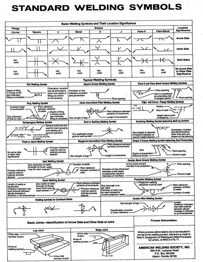
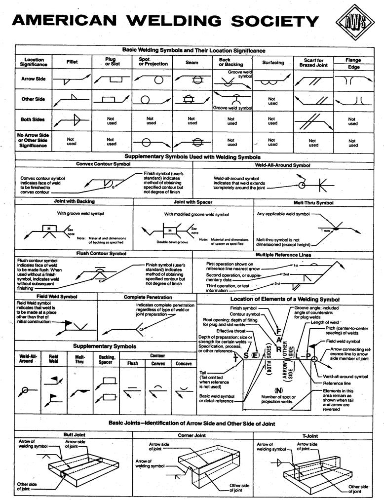
Welding Symbols
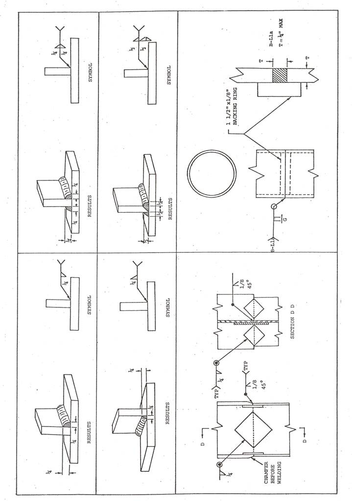
Welding symbols were formulated by the American Welding Society and have since been standardized for the entire welding industries. These symbols convey the requirement set forth by the designer in a given area to meet the calculated stress load that will be applied. It is therefore important that the inspector understand their meaning thoroughly, and apply it correctly at all times.
A table of the most commonly used symbols has been prepared for this IM.
SECTION V
Inspector Duties
The inspector's primary function is that of inspecting the contractor work and to see that it meets the requirements of the specifications. If the contractor should request advice on changes or modifications in any way the inspector should cooperate in every way possible to obtain this information from the proper authorities. However, if changes or modifications are approved it must always be with the definite understanding that the contractor has the full responsibility for the quality of the final product.
An inspector should keep in touch with the activities of the contractor personnel. Generally, the contractor does not intentionally disregard contract requirements. However, errors can occur through worker carelessness or lack of familiarity on the part of the contractor. While the correction of any errors remains the responsibility of the contractor, the inspector should make certain these mistakes are brought to the contractor's prompt attention. Early correction of a mistake can oftentimes produce a satisfactory product.
The inspector duties will follow the general headings below:
1. Interpretation of the Plans & Specifications
2. Verification of Welder & Procedure
3. Verification of Written Welding Procedures
4. Production Welding Checks
5. Keeping Records & Reporting
Interpretation of Plans & Specifications
The inspector should become familiar with the construction details pertaining to welding. Oftentimes notes on the plans will explain a welding detail or method of prescribed welding. It is also necessary to know any special provisions or proposal that may be specified in a particular contract document. These special provisions or proposals often carry the welding documentation that will require special treatments necessary to obtain a satisfactory weld.
The inspector should not accept responsibility for deviations until specifically authorized to do so. Many unknown stresses may be encountered when changes or deviations take place, which could affect the structure adversely.
Verification of Welder & Procedure
The specifications that apply to the making of weldments require qualification of the welder. The procedure to qualify these welders is specified in AWS and the Standard Specifications. It is the inspector's duty to verify that each welder who works under these specifications has been properly qualified according to these specifications. The inspector must verify the test data and the results of the tests. Thus, one very important duty of the inspector is to see that the welder only works within the qualification limits. Field welders are qualified for three years, a requalification test is necessary to keep a welder's qualification updated. Other limiting variables to be verified by the inspector are the types of weld, groove or fillet, the position to be welded and the thickness of the joint to be welded.
One specification of weldments is the requirement of a prescribed welding procedure. These welding procedures are prescribed for the type of joint to be used, and for the grade and thickness of the base metal to be employed for the work. These procedures are necessary to produce welded joints with acceptable mechanical properties in accordance with the specifications.
Before any welding is started the inspector should verify that the welding procedures have been established. For the most part the procedures required for field welding are set forth in this IM. These instructions include the necessary welding procedures for the various types of welding to be performed. However, reinforcing bars are not covered in this manual.
It is also the inspector's duty to note if any changes in a welding procedure are in excess of the limits set out in AWS. When a modified procedure is necessary the inspector should be sure it is not used in the structure until it has had final acceptance by the Construction and Materials Bureau and the Design Bureau.
Once a qualification procedure has been accepted or approved it will remain approved until one of the essential variables has been changed. These variables and their limits can be found in AWS.
Verification of Written Welding Procedures
The welding of some items has become so routine that they have become to be known as prequalified joints. These joints are of a basic design and the welding of them requires very little in the way of a written procedure. The inspector will find a list of these prequalified joints in the AWS book.
While some of these prequalified joints are basic fundamentals of a joint and for small weld areas, the same joint may be used in a bridge that will extend for the entire length of the structure. The more the length of any joint is involved in a procedure the more it becomes a mandatory requirement and its acceptance should be the responsibility of those people more familiar with welding problems. The field welding inspector should at no time take it upon himself/herself to accept a welding procedure but should be familiar enough with it to enforce it within the limits of the AWS Specifications.
Selection of Production Test Samples
Not very often does a specification call for production test samples of field welding, but it does happen on occasions and therefore the inspector must have an idea of what is expected in taking these samples. The specification will state if the production test is to be non-destructively tested. It will also state what type of non-destructive test is to be performed.
When non-destructive tests are to be performed it will usually be in the form of radiographic inspection. The number or frequency of radiographs to be taken will be included in the specification document. However, when spot radiographic inspection is called for the inspector may be required to make the decision of when the radiographic inspection is to be made. These tests may be made by chance or in accord with an established order. In either case the contractor and the state are definitely concerned about new welders and some early radiographic inspection is highly desirable, followed by less frequent inspection once the welder has proven their consistent ability.
Additional non-destructive testing may be performed by magnetic particle inspection, trepanning, ultra-sonic, dye penetrant, metallurgical examination, mechanical testing to destruction of run off tabs or other detailed examinations.
Records & Reports
Any work performed in the field that requires inspection or tests will also require records. However, required or not, an inspector should keep a good record of their work. This may be in the form of a set of notes or as detailed as the Resident Construction Engineer requires.
It is also the inspector's duty to check all records for detailed accuracy, in accordance with the contract documents, and to have them available when required. Any records that may require a contractor's signature should be prepared by the contractor and not by the inspector.
SECTION VI
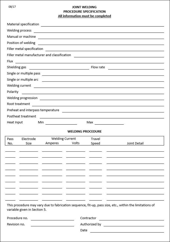
Specifications for Welding Procedures
Many factors contribute to the end result of any welding operation. Because of the complexity it is desirable and essential that the vital parts, associated with the welding of a joint, are properly detailed to permit a clear understanding of the intended weld to all concerned. Generally, welding procedures have to be proved adequate by either qualification tests or enough prior use and experience to guarantee dependability. The sole purpose of welding procedures is to describe the details that are to be followed in the welding of specific materials or type of joint.
Description & Details
The details of a welding procedure specification when written must be in accordance with the contract specifications and within good welding practice. They must be sufficiently detailed including welding sequence to insure welds that will satisfy the contract specifications.
The following is a list of details that are normally covered in a welding procedure specification for the shielded metal-arc process. Other welding processes may have some specification changes of varying degrees, and when used in the field a reference to AWS will most certainly be needed.
WELDING PROCESS - SHIELDED METAL-ARC
Filler Metal - Unless otherwise specified in the contract the electrodes shall be E-7016, E-7018.
Base Metal - ASTM A709, Grade 36, or 50 or 50 W structural steel, ASTM A-252 steel pipe, ASTM A500 seamless steel structural tubing or A501 structural steel tubing
Type of Current -AC, DC reverse (electrode positive) or DC straight (electrode negative).
Joint Design - Single bevel (with backing) double bevel, square butt welds, or fillet welds, and the thickness of the base metal.
Welder Qualification - Welder qualified by tests given by an accredited AWS testing facility.
Preparation of Base Metal – For materials up to 4 in. thick a max surface roughness value of 1000 µin. is permitted.
Joint Welding Design - Details that influence weld quality in terms of specification requirements. These details help determine the soundness of welds, and influence the structural properties of the finished joint.
Welding Position - Such as flat, horizontal, vertical or overhead
Preheat Temperature - Unless otherwise specified in the contract documents the preheat temperature shall be as specified in the AWS Bridge Welding Code. (See IM 560, the supplement to this IM).
Interpass Temperature - Equal to minimum preheat temperature at all times. Maximum temperature is not critical provided the heat input during welding is not excessive. However, if heat treated steels are used the maximum temperature will be found in the AWS Code or the contract documents.
Additional Details
Some additional details that may not be mentioned in the welding procedure specification but still have adverse effects on the welding joint are summarized in the following paragraphs.
The indiscriminate use of peening shall not be permitted. Peening can be very detrimental to a weld if not properly used. However, the inspector should not confuse the use of the chipping hammer with peening a weld. Chipping hammers are required for the cleaning of slag from a weld. The definition of peening, in accordance with the AWS Code is, “the mechanical working of metals using impact blows or hammer blows.”
Excessive heat input during welding can also be detrimental to a weld. Therefore a controlled heat input is a must for a good weld. Cracks may result from welding processes involving large heat inputs. In the arc welding process the heat input is lowered by reducing the current or by increasing the travel speed while maintaining the same current level. This explanation then reveals to us that, the stringer bead is far superior to the weaving method in which the forward travel speed is drastically reduced while the current level remains constant.
When a weld is not completely satisfactory upon completion, local sections may have to be removed for repair. This shall be done by one or by a combination of the following approved processes; grinding, or air-arc gouging. These are the same methods that are permitted in preparing the joint for the first time. The repair weld shall be made by the same process and procedures as the initial weld.
Non-destructive testing of field welds is not made unless called for in the project specifications or directed by the engineer. Visual inspection of the welding is normally all that is required to be done by the inspector.
Postheat treatment of welds on structures is sometimes performed by a heat treatment of annealing process in order to develop the required mechanical properties or dependability as required. While this does not apply to the ordinary field welding work there are occasions when it has been called for. When postheat treatment is necessary it shall be part of the procedure specification and the inspector will be required to make sure the temperature is within the limits specified by the use of temperature sticks.
Welding procedure specifications are usually called for on the contract documents and then established by the contractor. Procedures that have the same basic fundamentals have been deemed as prequalified by the AWS.
SECTION VII
WELDMENT DEFECTS
Weldment defects can be classified into three groups:
1. Drawing or dimensional variations
2. Structural discontinuities within the weld
3. Physical or chemical properties of the weldment
Drawing or Dimensional Defects
The making of satisfactory welds in regard to dimensional defects depends upon keeping within the specified dimensions for the size and shape of welds and the finished dimensions of the product. Departure from the dimensions in any respect should be regarded as dimensional defects and must be corrected before the final acceptance of the weldment can be made. Defects of this nature may be further subdivided as follows:
A. Incorrect Joint Preparation:
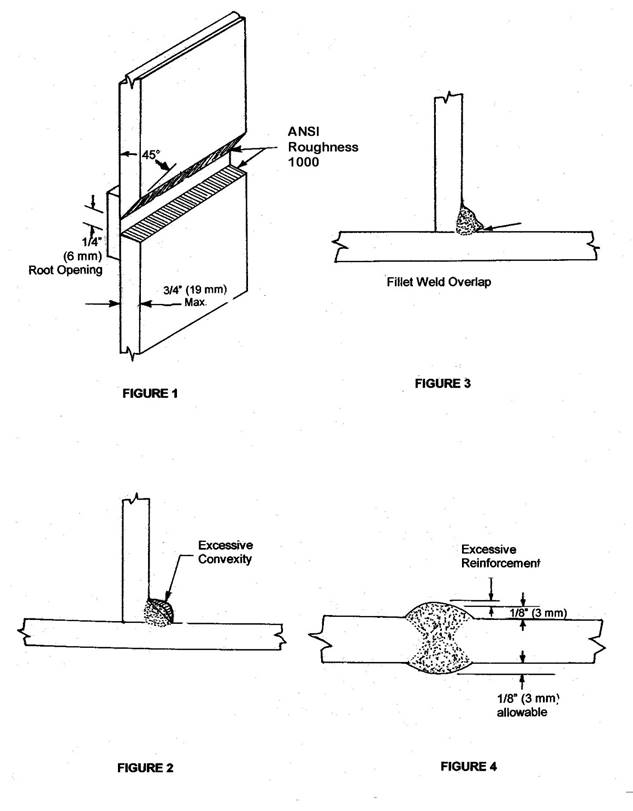
Established welding procedures require proper joint dimensions and preparation for each joint according to the thickness of the material being welded. The failure of an inspector to require these criteria may result in a greatly increased tendency to produce the weld defects listed under structural discontinuities within the weld. Therefore it is very important that all joint preparations are the same as shown in the specifications (See Figure 1).
B. Incorrect Weld Profiles & Sizes:
The profile of a finished weld can have a considerable effect upon its performance under load. The profile of one layer of a multipass weld can have an effect on the next pass in that it may cause slag inclusions or incomplete fusion to occur between the passes. Requirements concerning these defects are in AWS under the article entitled Weld Profiles and the inspector should have a good working knowledge of them. Failure to conform to these requirements constitutes a weld defect. Permissible tolerances and corrections for these various defects will also be found in AASHTO / AWS D1.5, Chapter 3 Workmanship.
Overlap is a condition, which tends to produce notches, which are dangerous, due to the resultant concentrated stress under load. It is considered defective welding because the effective size of the fillet is reduced. It is also very hard for an inspector to be sure of the true fillet size, since the true size is governed by inscribing an isosceles right triangle inside the fillet weld cross section. Overlap is generally caused by improper welding technique or by improper electrical conditions. The inspector should look for overlap conditions primarily on the lower leg of fillet welds, but it can also be found at times on the last pass, or reinforcement pass of groove welds (See Figure 2).
Excess convexity, like overlap, tends to produce notches. What has been said about overlap is also true of excessive convexity. Excess convexity is also harmful in the case of an intermediate pass in a multi-layer groove weld, because slag inclusions or incomplete fusion can occur on a succeeding pass if corrective measures are not taken (See Figure 3).
Excess concavity is usually associated with fillet welds. The actual strength of such welds is less than that of a standard size weld since its throat thickness is less than normal when measured by the length of the fillet leg. This condition is usually caused by excessive welding currents or arc lengths.
Excessive weld reinforcement is also undesirable in that it tends to stiffen the section and establishes notches that help create undesirable stress concentrations (See Figure 4).
C. Incorrect Final Dimensions:
All weldments are fabricated to meet a plan dimension. The inspector and the welder must be aware of how much shrinkage can be expected at each weld joint and how much warpage will occur in the joint.
If the inspector visualizes the welding of a simple V on a simple plate and knows that the welding heat causes shrinkage in each pass, then they can also visualize the ends of the plate curling up. These heat shrinkage stresses will tend to produce cracking.
On welds that are designed to prevent shrinkage and warpage or welds that are restricted by manuals devices it is obvious that while shrinkage must still occur it is restricted and thus produces shrinkage stresses that will tend to produce cracking.
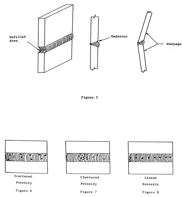
The inspector should review the drawings to determine which dimensions are critical and then discuss the weldment dimensions and tolerance with the welder so he/she will devote major efforts to these critical areas (See Figure 5).
Structural Discontinuities
When making manual shielded metal-arc welds, various types of defects may occur. These defects can be classified as structural discontinuities and consist of porosity, slag inclusions, lack of fusion, cracks etc. This terminology is used here to denote an interruption in the soundness in weld metal itself and not change in the metallographic structure of the metal such as laminations, scabs etc.
Porosity is gas pockets or voids in the weld metal which are free of any solid materials, such as slag. It is formed as a result of gases driven from the weld metal during solidification of the weld. Porosity is generally classified into different groups as follows: scattered, clustered and linear.
Scattered porosity occurs throughout the weld metal and the voids may vary in size from microscopic to slightly over 1/8 in. (See Figure 6).
Clustered porosity occurs in groups and may generally be associated with a change in welding conditions (See Figure 7).
Linear porosity occurs throughout the length of a weld and the voids are in a line with respect to the axis of the weld. This type of porosity generally comes in the root pass and usually can be traced to the inadequate preparation of the joint (See Figure 8).
The causes of most types of porosity can be controlled by avoiding the use of excessive currents and excessive arc lengths, the removal of rust prior to welding and proper preparation of the joint.
Slag inclusions are entrapped non-metallic solids in or near the weld metal and vary in size and location. Slag in molten weld metal will rise to the surface unless restrained by another force. When welding by any of the metal-arc processes slag or gas may be formed or forced below the surface of the molten metal by the stirring action of the electric arc. Slag can also flow ahead of the arc and thus cause metal to be deposited over it.
Slag can also form on a root pass of a V weld if the root opening is too small to permit the arc to heat the bottom of the recess to a high enough temperature to allow the slag to float to the surface (See Figure 9). The welder can create similar conditions to this by having undercutting or excessive convexity in a weld bead, or using too large an electrode in the root pass. This type of slag inclusion is elongated and usually of considerable size and thus the strength of the joint is reduced considerably.
When slag is forced into the molten metal or is formed by chemical reaction, its appearance is the same as porosity on a radiographic film. Slag of this type is most likely found in overhead welding.
The inspector should realize that most slag can be prevented by the welder using good sound welding practices, such as: proper preparation of the groove before each weld bead is deposited. Use care to correct contours that are outside specifications and the use of preheat to retard the weld metal solidification.
In making multiple pass welds the slag from the center of the pass is easily removed but the edges are usually more difficult. This slag area is often referred to as bond-line slag. In most cases this slag can be re-melted and rise to the surface in the next pass but it can also remain and will show up in a radiograph as elongated slag at the bond line. The welding inspector should use good judgement on this part of the inspection in seeing that the welder does a good job of removing the slag between passes but that a tiny amount of slag left at the bond line should work out during the next welding pass.
Where a welder does an imperfect job of slag removal and another welding pass is put down over it, the slag will tend to interrupt the arc and fusion of the weld metal is prevented along with the re-melting of the old slag. The inspector will find the result of this as scattered slag inclusions.
Incomplete fusion is another structural discontinuity of which the inspector must be aware. Incomplete fusion is sometimes referred to as lack of fusion. Actually, it is best described as the failure of weld metal to fuse to a base metal or other weld metal and may occur at any place in a weld. The cause for lack of fusion is due to the failure of raising the temperature of the base metal to the fusing point or the failure to dissolve by fluxing, the oxides or other foreign material on the surface of the metal to be welded. The best inspection for incomplete fusion is ascertaining the surfaces to be welded are free of all objectionable material (See Figure 10).
The term, undercut, is used primarily to describe the reduction of the base metal thickness at a line where the last bead of weld metal is fused to the surface or at the toe of a weld. It can occur on both groove and fillet welding but is most frequently found on the vertical leg of a horizontal fillet or the top side or a horizontal groove. Undercutting of both types is usually due to a technique employed by the welder, although magnetic arc blow can also be a factor. Undercutting can be detected by visual inspection and a tolerance for it has been set up in the AWS under the Article, “Weld Profiles” (See Figure 11).
Cracks in welded joints are results of a localized stress that at some point has exceeded the ultimate strength of the material. Materials that have good ductility under a single stress have been known to fail with little deformation under a multi-directional stress system. As discussed before, the unfused area of the root may result in cracks. Any material that is hard or brittle is more subject to cracking than a ductile one, therefore it is important that the inspector makes certain the right and properly cared for electrodes are used. The ability of weld metal to remain intact during the welding operation is due to the composition and structure of the weld metal. Once a crack has started it will continue through additional layers of weld metal as deposited unless it is repaired before additional layers are made.
Known causes of cracks are: the wrong use and manipulation of electrodes, improper electrical conditions, travel speed and lack of preheat.
Different types of cracks are: transverse, longitudinal, crater and base metal. The first three types are usually visible cracks that are easily found. The base metal cracks are much more difficult and test methods may be required to discover them. Like the name implies, the cracks are in the base metal and sometimes are under the weld bead (See figure 12).
Crater cracks are small and usually star-shaped and found in the weld crater itself. They start at the center of the crater and extend out to the end. Crater cracks are not detrimental to the weld metal if they are repaired. However, these may be starting points for longitudinal weld cracks when left unrepaired.
Various types of surface irregularities may occur during welding. These irregularities can vary from actual holes in the weld to surface roughness of the metal or excessive spatter. Improvement of these conditions is usually obtained by changing the electrical conditions. It is important to remove the cause of these irregularities because they can cause slag entrapment. In high quality welding it is not safe to assume that these irregularities will fuse out during the placement of the next weld bead. Good welding practice dictates their removal by grinding or chiseling.
The more uniform the weld bead surface, the better the eye appeal. Good welding that is poorly finished should not be excused except under unusual conditions even though the integrity of the job is beyond question. Such unusual conditions would be a great magnetic disturbance at the location of the weld. At times piling are driven too close to the ground for splicing and the welder has to bend over or lie down in order to make the splice.
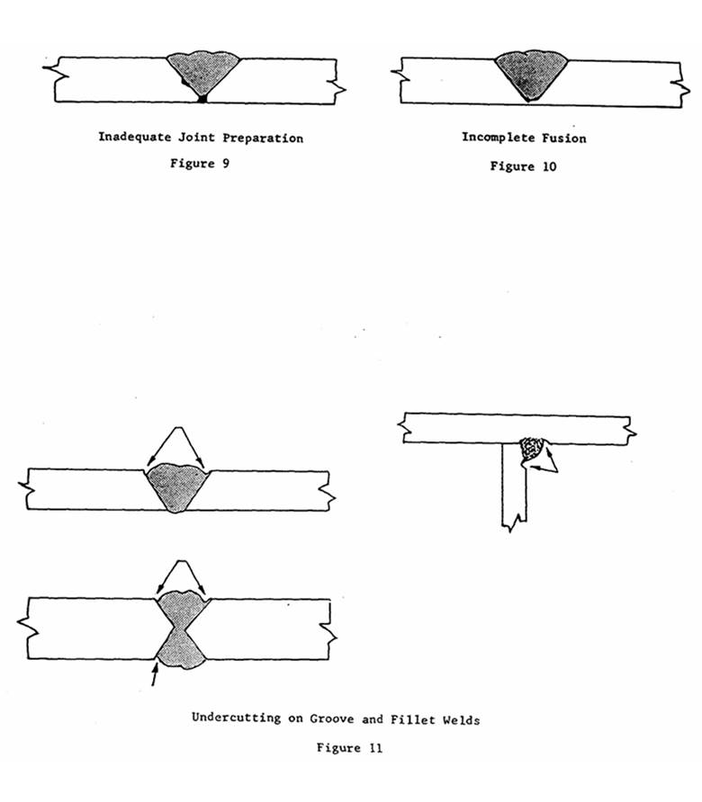
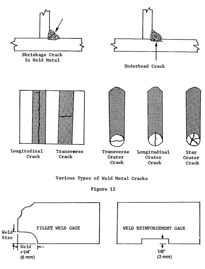
Figure 13
Physical & Chemical Properties of Weldments
The physical and sometimes chemical properties are required on all weld metal. The properties are dependent upon the specifications involved. Any departure from these specifications must receive the approval of the engineer. The AWS D1.5 Bridge Welding Code specifies the type of electrode that must be used for weldments.
Filler metal (electrodes) shall be selected from the AWS D1.5 Bridge Welding Code as listed in tables 4.1 and 4.2.
A certificate of conformance from the manufacturer shall be required if the selected filler metal (electrode) is not listed in the AWS D1.5 Bridge Welding Code.
Certificate of conformance must be submitted along with the weld procedure for acceptance and approval.
All filler metal (electrodes) certificates shall include a statement indicating the steel meets the requirements of IM 107, Group 2, Buy America.
Methods of Testing
Various methods of testing are available to a weld inspector in a fabricating shop, but to a field weld inspector, the best inspection must be made by visual inspection and at best a few accessories such as gauges or a ruler. The following table has been set up for an inspection guide. Since radiographic inspection of field welding is rarely specified the field inspector's substitute is a periodic close observance of the welder's technique.
|
TESTS FOR WELDS |
|
|
Defect |
Methods of Testing |
|
|
|
|
DIMENSIONAL DEFECTS |
|
|
Warpage |
Visual inspection with proper mechanical gauges |
|
Incorrect joint preparation |
Visual inspection - Comparison with workmanship sample |
|
Incorrect weld size |
Visual inspection with proper mechanical gauges |
|
Incorrect weld profile |
Visual inspection with proper mechanical gauges |
|
Incorrect final dimensions |
Visual inspection with proper mechanical gauges |
|
|
|
|
STRUCTURAL DISCONTINUITIES |
|
|
Porosity |
Radiographic - Magnetic Particle - Ultrasonic |
|
Slag Inclusions |
Radiographic - Magnetic Particle - Ultrasonic |
|
Incomplete fusion |
Radiographic - Magnetic Particle - Ultrasonic |
|
Inadequate joint penetration |
Radiographic - Magnetic Particle - Ultrasonic |
|
Undercut |
Visual inspection |
|
Cracks |
Visual inspection - Radiographic - Magnetic particle |
|
Surface |
Visual inspection - Comparison with workmanship sample |
|
|
|
SECTION VIII
NON-DESTRUCTIVE TESTING
The purpose of nondestructive testing is to detect weld discontinuities in weldments without impairing the usefulness of the material. There is an increasing growth in the use and types of testing available to the inspector. Currently, the methods accepted for weld inspection are visual, magnetic particle, liquid penetrant, radiographic, ultrasonic, eddy-current and leak and proof test techniques.
Under any one circumstance, one of these methods may be more suitable for that purpose than any one of the others.
Most nondestructive testing is expensive in that the operator of the equipment must be thoroughly trained and acquainted with the theory and application of the equipment. Therefore, the Bridges & Structures Bureau attempts to eliminate any field welding in critical areas as much as possible and thereby relies on visual inspection for the majority of its field welding.
Visual Inspection
The visual inspection of weldments is of the first order of importance even when radiographic or other nondestructive means of testing is specified. It is the most important part of quality control. Visual inspection is also the most informative with regard to the general conformity of the weldment to specifications. It is the most extensively used of any method of inspection.
Visual inspection can be divided into four titles: inspection skills, inspection before welding, inspection during welding and inspection after welding.
Inspection Skills
The field inspectors should develop a definite procedure to insure adequate coverage of the various steps of welding. They must be familiar with the welding specifications, workmanship and all phases of welding.
Before Welding
Details to check before the welding starts are:
1. Material to Be Welded
2. Welder Qualification Certificate
3. Welder Equipment & Electrodes
4. Correct Bevel & Smoothness of Edge Preparation
5. Root Opening
6. Clearance of Backing Strip or Ring
7. Overall Alignment & Fit Up
8. Welding Procedure
During Welding
Details to check during the welding are:
1. Preheat & Interpass Temperature
2. Cleaning, Chipping, Grinding or Gouging
3. Structural Discontinuities
4. Postheating Temperature When Specified
After Welding
Details to check after the welding are:
1. Dimensional Accuracy of Weldment
2. Conformity to Drawing Requirements
3. Acceptability of Welds With Regard To Appearance
4. Presence of Any Unfilled Craters, Undercuts, Cracks, Overlaps
5. Postheating Temperature When Specified
Nondestructive Testing of Field Welded Steel Pile
The engineer may require nondestructive testing (NDT) of field welded steel pile.
Personnel performing NDT shall be qualified in conformance with the American Welding Society (AWS) D1.1.
Twenty-five percent of the pile weld joint will be tested on one pile per 10 piles with a minimum of two piles in each foundation.
Acceptance criteria shall be in accordance with AWS D1.1 for cyclically loaded non-tubular connections.
The contracting authority will be responsible for the initial travel costs for the NDT agency and for the testing described above. The contractor will be responsible for all costs associated with additional testing and weld repair or replacement.
If unacceptable discontinuities are found based on the NDT agency / engineer’s review, the entire length of the pile weld shall be tested and two additional pile weld joints will be tested for each weld joint that is found to be unacceptable.
All welds tested with NDT that do not meet the requirements of the AWS code shall be repaired or replaced at the engineer’s discretion.
After any welds have been repaired and / or replaced, additional NDT testing shall be performed to ensure the repairs are satisfactory. This testing shall include all of the repair area plus at least 2 inch on each side of the repaired area.
Summary
Visual inspection is invaluable as an inspection method but caution must be used in drawing conclusions. The inspector should not judge a good surface appearance in itself as high weld quality, but rather base judgement on evidence afforded by observations made prior to and during the welding along with the good weld appearance.
Gauges and workmanship samples are also useful to the inspector and he/she should familiarize themselves in their use. Gauges can be readily made from a thin piece of sheet metal or cardboard if necessary. Figure 13 gives the basic dimensions necessary for simple gauges.
SECTION IX
WELDING EQUIPMENT
Most field welding machines are portable, that is, they are on a truck and can be moved around. The welding machine is usually a generator driven by a gasoline-powered engine and puts a DC current that may be reversed by changing the leads. The welding machine must contain a gauge or some means of determining the amperage output along with some method of increasing or decreasing the amperage as desired. The leads shall be in good condition with unfrayed connections at both ends.
Good quality electrodes are a must. Welding manufacturers produce good quality electrodes that conform to the AWS Code test requirements; however, this does not ensure their good quality when delivered to the job site. The welder should discard any damaged electrodes. When using low hydrogen electrodes, he/she must furnish them from undamaged hermetically-sealed containers and have an oven for maintaining their dryness.
The welder's cleaning tools should consist of a chipping hammer and a wire brush. A cold chisel and a hammer may be substituted for the chipping hammer.
A cutting torch must also be available for cutting, beveling and fitting up of the joints of field welds when required. A grinder is also necessary for smoothing out rough cuts and for the removal of a bad weld. Few welders are so skilled with a torch that grinding is not necessary.
The welder must have knowledge of the joint to be welded. Before welding, the inspector should check this knowledge against the information furnished to the Resident Construction Engineer and make certain that it conforms to requirements outlined in these instructions.
All welders shall be responsible for being able to prove that they have a valid AWS welding certification card or a valid IA DOT welder certification card if issued prior to April 18, 2017.
TEMPERATURE STICKS
|
Fahrenheit Temperature Sticks by Tempil are available as follows: |
|||
|
6o increments |
100o-350o |
50o increments |
650o-900o |
|
2o-13o increments |
350o-500o |
Approx. 25o increments |
900o-1050o |
|
5o increments |
500o-650o |
50o increments |
1050o-2500o |
SECTION X
INSPECTOR RESPONSIBILITIES
Under Section V the duties of the inspector were described in a general way but detailed inspection was not spelled out. In Section VII a detailed list of items was given as a check list for the inspector. It is now possible for the inspector to be familiar with the inspection required and be able to follow the instruction in this IM with a sense of responsibility.
Consultation with the welder is one responsibility the inspector should take care of as soon as it is known who the welder is going to be. If a visit with the welder before he/she comes on the job is possible, this is even better than a discussion after their arrival. After having checked their certificate, the class and polarity of the electrode should be discussed along with the proper preheat and interpass temperature. Consult with them on the need for proper joint preparation and fit-up. Give their first joint special attention so that caution will be used throughout the job.
WELDING OF PILING
A description of the various types of piling and the welding is well defined on pages 43 through 46 of this IM. The inspector who follows the procedures outlined in the instructions will be able to carry out the inspection duties with great care. See Appendix A.
WELDING OF SHEAR STUD CONNECTORS
Stud welding must comply with the AWS Code D1.5, Section 7. Only studs with a qualified stud base may be used. Those currently approved are listed in IM 453.10, Appendix A. Any other brand must submit their qualification tests to the Iowa Department of Transportation, Construction and Materials Bureau, in Ames for approval.
A manufacturer studs certification and certified test reports shall be required and shall be as outlined in the AWS Code D1.5, Paragraph 7.3.3. The manufacturer test reports shall be dated (been made) not to exceed the six months period before delivery of the studs.
Only automatically timed stud welding equipment (welding stud gun), shall be used for stud welding on Iowa’s projects. No other welding processes shall be allowed nor can be accepted.
Stud welding operators are not required to be certified welders but must be qualified.
These automatically timed stud welding Equipment (stud guns) shall be connected to a suitable source of direct current electrode negative (DCEN) power. Welding voltage, current time, and gun settings shall be based on past practice, recommendations of stud and equipment manufacturer, or both.
While in operation the stud gun shall be held in position without movement until the weld metal has been solidified.
If two or more stud welding guns are to be operated from the same power source, they shall be interlocked so that only one gun can operate at a time and so that the power source has fully recovered from making one weld before another has started.
Operator Qualification: Two stud shear connectors shall be welded on a trial basis to a test steel plate similar to the specified member in thickness and properties (type & grade). All test studs shall be welded in the same position as required. After allowing the studs to cool, the welded studs shall be visually inspected for a 360º flash (requirements) and then bent to an angle of 30º from their original axis by sticking with a hammer or bending with a pipe. If failure does not occur in the trial weld zone of either of the stud, welder will be qualified and be allowed to begin the stud welding on the actual girders and the preceding testing bending procedures shall be repeated.
If failure does occur in the weld zone of either stud, the procedures shall be corrected and two more studs shall be welded to another test plate. If either of the second two studs fails, additional welding shall be continued on separate test plates until two consecutive studs are welded and found satisfactory.
When two consecutive studs have been accepted, the inspector shall then document the test in his / her file with the name of the operator and the date of the test. After operator qualification has been completed and the stud welding process has started, the first two studs shall be tested for the 360º flash and bending the two studs to 30º. Qualification of each operator must be documented at the start of each project. Stud welding testing and evaluation shall be performed at the beginning of each production day of stud welding.
Welding shall not be done when the temperature of the base metal is below 0°F or when the surface is wet or exposed to rain or falling snow. When the temperature is below 32°F one additional stud in each 100 studs welded shall be tested (see Note 1) in addition to the first two tested for each production day.
Note 1: Test shall consist of bending the studs after they are allowed to cool to an angle of approximately 30° from the original axis by striking the studs on the head with a hammer.
The stud base shall not be painted, galvanized, nor cadium-plated prior to stud welding.
Studs shall be free from rust, rust pits, scale, oil, moisture, and / or any other deleterious matter that may adversely affect the welding process.
The areas to which the studs are to be welded shall be free of scale, rust, moisture, and any other injurious material to the extent necessary to obtain satisfactory welds. These areas may be cleaned by grinding, wire brushing, and / or scaling.
The arc shields or ferrules shall be kept dry. Any arc shields which show signs of surface moisture from dew or rain shall be oven dried at 250° F for two hours before use.
Longitudinal and lateral spacing of stud shear connectors (Type B – see note # 2) with respect to each other and edges of beam or girder flanges may vary by a maximum of 1.0 inch from the location shown in the drawings. The distance between studs shall not be less than 1.0 inch, and the distance from the edge of a stud base to the edge of a flange shall not be less than 1 ½ inch.
After the studs have been welded to the bridge member a visual inspection shall be made and each stud shall be given a light blow with a hammer. Any stud which does not have a complete end weld (360° fillet), any stud which does not emit a ringing sound from the light hammer blow, shall be struck with a hammer and bent 15° from the correct axis of installation, and in the case of a defective weld. The stud shall be bent 15° in the direction that will place that defective area of the weld in the greatest tension area of the studs that crack either in the weld or the shank, shall be replaced.
Note: The greatest tension area of the stud is the area in the opposite direction of the defective area.
Note 2: Stud welding shall be performed as per manufacturer’s recommendations (welding requirement, base surface temperature, surface preparation, stud gun, power source, stud diameter, gun lift and plunge, total welding lead length, amperage, and welder’s qualifications).
If 10% of the studs applied to any bridge member requires bending, the welding shall be suspended until the necessary changes are secured to produce satisfactory studs on the subsequent members. If conditions warrant, the inspector may require additional studs to be bent.
Note 3: There are two types of studs Type A Studs have a lower strength and are for general purpose use and are prohibited for shear transfer in composite construction. The higher strength studs, Type B are used as an essential component of composite beam construction. Only Type B studs have a minimum specified yield strength, necessary for proper in-service performance.
After welding, arc shields (ferrules) shall be broken free from studs to be embedded in concrete and as well from all other studs.
Note 4: The fillet weld profiles shown in Figure 3.3 of the AWS D1.5 code do not apply to the flash of automatically timed stud welds. The expelled metal around the base of the stud is designated as flash in accordance with Appendix V of this code. It is not a fillet weld such as those formed by conventional arc welding. The expelled metal, which is excess to the weld required for strength, is not detrimental but, on the contrary is essential to provide a good weld. The containment of this excess molten metal around a welded stud by the ferrule (arc shield) assists in securing sound fusion of the entire cross section of the stud base. The stud weld flash may have nonfusion in its vertical leg and overlap on its horizontal leg, and it may contain occasional small shrink fissures or other discontinuities that usually form at the top of the weld flash with essentially radial or longitudinal orientation, or both, to the axis of the stud. Such nonfusion, on the vertical leg of the flash, and small shrink fissures are acceptable.
WELDING FOR SUPPORT OF FLOOR FORM JOISTS & FINISHING MACHINE RAILS
Unless otherwise authorized by the engineer, any welding to the top flange of steel members for supporting floor form joists and finishing machine rails will not be permitted.
SECTION XI
STRUCTURAL FIELD WELDING
DESCRIPTION
Field welding members using the shielded metal arc and flux-cored arc welding processes
MATERIALS
Electrodes for shielded metal arc welding (SMAW) shall conform to the requirements of the latest edition of ANSI/AWS A5.1, Specification for Mild Steel Covered Arc Welding Electrodes, or ANSI/AWS A5.5, Specifications for Low-Alloy Steel Covered Arc Welding Electrodes.
Electrodes for flux-cored arc welding (FCAW) shall conform to the requirements of the latest edition of ANSI/AWS A5.20, Specification for Carbon Steel Electrodes for Flux-Cored Arc Welding, or ANSI/AWS A5.29, Specification for Low-Alloy Steel Electrodes for Flux-Cored Arc Welding.
Electrodes for SMAW and FCAW processes shall be selected from the AWS D1.5 Bridge Welding Code. Electrodes Certificate of Compliance shall include a statement from the manufacturer stating that the electrodes are melted and manufactured in the USA. For most structural steel construction, the applicable welding code is AASHTO/AWS D1.5, Bridge Welding Code, or ANSI D1.1, Structural Welding Code – Steel. Tests must be conducted on electrodes of the same class, size and brand and manufactured by the same process and with the same materials as the electrodes to be furnished. Test results for electrodes shall be submitted every 12 months for renewal.
Table 1 shows the classes of electrode required. Use electrode with the type of current, with the polarity, and in the positions permitted by AWS A5.1 and A5.5 for SMAW. AWS A5.20 and A5.29 Specifications govern for FCAW. Approval shall be obtained for electrode use on steel not listed in Table 1.
|
TABLE 1 |
|||
|
Classification of Electrodes Permitted |
|||
|
Type of Steel (ASTM Standards) |
Electrode Specification |
Process |
Filler Metal Requirements |
|
A36 A572, Gr. 50 A588 A242 A709, Gr. 36, or S |
AWS A5.1 or A5.5
|
SMAW
|
E7016 E7018 E7028 |
|
AWS A5.20 or A5.29 |
FCAW |
E7XT-1 E7XT-5 E7XT-6 E7XT-8 |
|
|
Weathering
A588 A242 A709, Gr. 50W
|
AWS A5.5 |
SMAW |
E8018-W E8016-C3 E8018-C3 E8016-C1 E8018-C1 E8016-C2 E8018-C2 |
|
AWS .29 |
FCAW |
E8XT1-W E8XTX-Nil E8XTX-Ni2 E8XTX-Ni3 |
|
|
A709, GR. HPS 70W |
AWS A5.5 |
SMAW |
E9018-M-HBR |
NOTE: Low-hydrogen electrodes applicable to the lower strength base metal may be used in joints involving base metals of different yield points or strength.
When welding fracture-critical applications, use electrodes meeting the diffusible hydrogen requirements for fracture-critical welding in AASHTO/AWS D1.5.
EQUIPMENT
The Contractor shall provide the following equipment: Electrode drying and storing ovens that can maintain the required temperatures specified in the AWS Code D1.5, Section 4, along with thermometers for checking and controlling the oven temperatures, preheating equipment that can maintain the entire joint at or above the specified temperature, approve equipment for checking preheat and interpass temperatures at all times while welding is in progress, welding equipment meeting the requirement of the approved welding procedure specification (WPS), and capable of making consistent high-quality weld.
CONSTRUCTION
PROCEDURE QUALIFICATION: The proper classification and size of electrode, arc length, voltage, and amperage for the thickness of the material, type of groove, welding positions, and other circumstances of the work shall be used.
For welding of main members, WPS for FCAW shall be qualified in accordance with AASHTO/AWS D1.5, before any field welding on a project.
Welders shall be qualified at an accredited AWS testing facility. Welders shall be confined and limited to welds only with the process and in the positions for which they are qualified.
FIELD WELDER CERTIFICATION: Before making any welds on structural steel, a welder must pass the AWS Code D1.5 qualification test for groove welds. ASTM A36 shall be used for test plates. Approved electrodes meeting the requirements of the AWS Code D1.5 and the approved WPS shall be used. Two bend specimens shall be prepared, tested and inspected for each test plate. The welder must be qualified at an accredited AWS testing facility (or by the IA DOT if the welder certification card was issued prior to April 18, 2017). Radiographic examination of welder and welding operator qualification test plates may be made in lieu of a bend test. Radiography procedure and test results shall comply with the AWS Code D1.5, Sections 5.26 and 5.27.
The field welder’s qualification herein specified will be considered as remaining in effect from the end of the month in which the test was taken, for a period of three years. Requalification may be required at any time there is a specific reason to question a welder’s ability to make sound welds.
A welder must also demonstrate to the Engineer a thorough knowledge of the required welding procedures together with the ability and desire to follow them and make welds of sound quality and good appearance.
For SMAW, a welder certified using EXX18 electrodes is qualified to weld with all approved SMAW electrodes up to E90XX to join metals with a maximum specified yield strength of 65 ksi.
WELDING STEEL CASING PIPE
1. Pipe – use only pipe meeting the requirements of ASTM A 139 / A 139 M Grade B, ASTM A 252 Grade 2 or ASTM A 53 Grade B. Casing pipe may be welded or seamless. Wall thickness shall be as specified in the contract document.
2. Joints –
a. Joints shall comply with American Welding Society AWS D1.1.
b. Weld shall be complete joint penetration welds for 360º (unless otherwise specified differently in the contract document) complete circumference of the pipe.
c. Welds shall comply with the requirements of IM 558
d. Welders shall be qualified according to IM 560 minimum requirement certified to 3G & 4G.
WELDING STEEL STRUCTURES
1. ELECTRODE CONDITION
a. SMAW. Electrodes with low-hydrogen coverings conforming to AWS A5.1, shall be dried in conformance with the manufacturer’s written drying instructions or dried for at least two hours between 450°F and 500°F. For electrodes with low-hydrogen coverings conforming to AWS A5.5, dry for at least one hour between 700°F and 800°F or as specified by the electrode manufacturer. If using electrodes from a newly opened undamaged hermetically-sealed container, drying is not required. Immediately after drying or removal from hermetically-sealed container, store electrodes in ovens held at a temperature of at least 250°F. Elapsed time permitted between removal of an electrode from the storage oven or hermetically-sealed container and use of the electrode is given in Table 2.
|
TABLE 2 |
|
|
SMAW Electrode Exposure Limits |
|
|
Electrode Type |
Exposure Time (Hours) |
|
E70 |
4 |
|
E80 |
1 |
|
E90 |
1 |
If electrodes are placed back in the holding oven before the times given in Table2 have lapsed, leave them in for at least four hours at 250°F before reusing. Do not redry electrodes more than once. Do not use electrode with flux that has been wet, cracked, or otherwise damaged.
b. FCAW: Protect or store welding wire coils removed from the original package to keep their characteristics or welding properties intact. Do not use coils or portions of coils that are rusty.
c. SPECIAL APPLICATIONS: For fracture-critical applications or when welding steel not shown in Table 1, dry electrodes in accordance with the manufacturer’s specifications and AASHTO/AWS D1.5.
2. ENVIRONMENTAL CONDITIONS: Do not weld when the air temperature is lower than 0°F; when surfaces are wet or exposed to rain, snow, or wind; or when operators are exposed to inclement conditions. Windbreaks shall be provided to protect the welding operations from winds greater than 5 mph.
3. ASSEMBLY & FITUP: Ends of members to be welded shall be prepared in accordance with the welded joint detail specified.
The parts to be joined by fillet welds shall be brought into as close contact as possible not separated more than 3/16 in. If the separation is 1/16 in. or more, increase the leg of the fillet weld by the amount of the separation. Keep the separation between faying surfaces of lap joints and of butt joints landing on backing strips to no more than 1/16 in.
4. PREHEAT: Preheat ahead of welding both groove and fillet welds (including tack welding) to the temperatures shown in Table 3. Keep preheat and interpass temperatures high enough to prevent cracks. The preheat temperatures shown in Table 3 are minimums, and higher preheats may be necessary in highly restrained welds. When the base metal is below the required temperature, preheat it so that parts being welded are not cooler than the specified temperature within three inches of the point of welding.
Measure preheat temperature on the side opposite to which the heat is applied at points approximately three inches away from the joint.
When possible, completely weld a joint before allowing it to cool below the specified temperature. Always deposit enough weld to prevent cracking before allowing a joint to cool. Do not allow preheat and interpass temperatures to exceed 400°F for thickness up to 1½ in. and 450°F for greater thickness.
|
TABLE 3 |
|
|
Minimum Preheat & Interpass Temperature |
|
|
For Welding with Low-Hydrogen Electrodes |
|
|
Thickest Part at Point of Welding |
Temperature |
|
Less than ½ in. |
70°F |
|
1/2 in. up to and including 1 1/2 in. |
150°F |
|
Greater than 1 1/2 in. |
Per AASHTO/AWS D 1.5 |
Preheat and interpass temperatures for the thicker plate thickness when joining steels of different thickness shall be used. If the base metal is moist, preheat it to 200°F before starting to weld.
WELDING PRACTICE
An approved procedure to control shrinkage and distortion shall be used. Weld as required by the contract or erection drawings. Do not change the location or size of welds without approval. Do not make temporary welds for transportation, erection, or other purposes on main members except as shown on the plans or approved by the Engineer. Use an approved method to mark each groove weld to identify the welder who performed the work.
Use the stringer bead technique where possible for groove welds. In vertical welding passes, progress upward, using a back-step sequence.
Begin and terminate groove welds at the ends of a joint on extension bars. Make edge preparation and thickness of extension bars the same as that of the member being welded, but extending at least two in. beyond the joint. After the weld is completed and cooled, remove extension bars with a cutting torch or arc-air gouging, and grind the edges smooth. If the grinding exposes any defects, clean them, fill them with weld metal, and regrind them to a uniform finish. Grind so that grind marks are parallel to the length, and avoid excess grinding of the parent metal. Clean and fuse tack welds thoroughly with the final weld. Remove defective, cracked, or broken tack welds.
Gouge, chip, or otherwise remove the root of the initial weld to sound metal for all groove welds, except those produced with the aid of backing before welding is started on the second side. Thoroughly clean the backside before placing the backup pass. For groove welds made with steel backing, thoroughly fuse the weld metal with the backing, and use backing that is continuous for the full length of the weld. Make a continuous length of backing by welding shorter sections together only under the following conditions:
· All splices in the backing shall be complete joint penetration (CJP) groove welds made with the same controls as similar CJP groove welds in the structure.
· Radiographic or ultrasonic test shall be used to assure weld soundness.
· All welding and testing of the backing shall be complete before the backing is used to make the structural weld.
ELECTRODE SIZE & WELD LAYER THICKNESS
1. SMAW
a. ELECTRODE SIZE: Use electrode with the following maximum size:
· 1/4 in. for all welds made in the flat position except root passes
· 1/4 in. for horizontal fillet welds
· 1/4 in. for root passes of fillet welds made in the flat position and of groove welds made in the flat position with backing and with a root opening of 1/4 in. or more
· 5/32 in. for welds made with low-hydrogen electrodes in the vertical and overhead positions
· 3/16 in. for all other welds
b. WELD SIZE & LAYER THICKNESS: The root pass shall be large enough to prevent cracking. Make layers subsequent to the root pass in fillet welds and all layers in groove welds of the following maximum thickness:
· 1/4 in. for root passes of groove welds
· 1/8 in. for subsequent layers of welds made in the flat position
· 3/16 in. for subsequent layers of welds made in the vertical, overhead, and horizontal positions
Make fillet welds passes no larger than:
· 3/8 in. in the flat position
· 5/16 in. in the horizontal or overhead positions
· 1/2 in. in the vertical position
2. FCAW
a. ELECTRODE SIZE: Use electrodes with the following maximum size:
· 5/32 in. for the flat and horizontal positions
· 3/32 in. for the vertical positions
· 5/62 in. for the overhead position
b. WELD SIZE & LAYER THICKNESS: Make weld layers, except root and surface layers, no thicker than 1/4 in. When the root opening of a groove weld is 1/2 in. or wider, use a multiple-pass split-layer technique. Use the split-layer technique to make all multiple-pass welds when the width of the layer exceeds 5/8 in.
Ensure that each pass has complete fusion with adjacent base metal and weld metal and that there is no overlap, excessive porosity, or undercutting.
Do not use FCAW with external gas shielding in a draft or wind. Furnish an approved shelter of material and shape to reduce wind velocity near the welding to a maximum of 5 mph.
Make fillet weld passes no larger than:
· 1/2 in. in the flat position
· 3/8 in. in the horizontal or overhead positions; and
· 5/16 in. in the vertical position.
WELD QUALITY
Weld quality and testing shall be in accordance with the drawings, specifications, and special provision as applicable.
CORRECTIONS
When welding is unsatisfactory or indicates inferior workmanship, the Engineer will require corrective measures and approve the subsequent corrections.
Use arc-air gouging when required to remove part of the weld or base metal. Do not use oxygen gouging. Backgouge splices or cut out defective welds using arc-air gouging by a welder qualified to make beam and girder splices.
Where corrections require depositing additional weld metal, slope the sides of the area to be welded enough to permit depositing new metal.
Correct defective or unsound welds either by removing and replacing the entire weld or as follows:
a. EXCESSIVE CONVEXITY: Reduce to size by grinding off the excess weld metal, leaving a smooth profile.
b. SHRINKAGE CRACKS, CRACKS IN BASE METAL, CRATERS & EXCESSIVE POROSITY: Remove defective portions of base and weld metal down to sound metal, and replace with additional sound weld metal.
c. UNDERCUT, UNDERSIZE, & EXCESSIVE CONCAVITY: Clean and deposit additional weld metal.
d. OVERLAP & INCOMPLETE FUSION: Remove and replace the defective portion of weld.
e. SLAG INCLUSIONS: Remove the parts of the weld containing slag, and replace them with sound weld metal.
f. REMOVAL OF BASE METAL DURING WELDING: Clean and form full size by depositing additional weld metal using stringer beads.
Where corrections require depositing additional weld metal, use a smaller electrode than that used for the original weld. Clean surfaces thoroughly before rewelding.
Remove cracked welds completely and repair. If crack length is less than half the length of the weld, remove the weld metal for the length of the crack plus two inches beyond each end of the crack, and repair.
Where work performed after making a deficient weld has made the weld inaccessible or has caused new conditions making the correction of the deficiency dangerous or ineffectual, restore the original conditions by removing welds, members, or both before making the necessary corrections; otherwise, compensate for the deficiency by performing additional work according to revised and approved design.
Cut apart and reweld improperly fitted or misaligned parts.
Straighten members distorted by the heat of welding using mechanical means or the carefully supervised application of a limited amount of localized heat. Do not let heated areas exceed 1200°F as measured by temperature-indicating crayons or other approved methods for steel up to 65,000-ksi-yield strength. Do not let heated areas exceed 1100°F for higher-strength steels. Keep parts to be heat straightened substantially free of stress from external forces except when mechanical means are used with the application of heat. Before straightening, submit a straightening procedure to the Engineer for approval.
SECTION XII
Welding of Railroad Bridge Deck Floors
Railroad bridges that span highways are designed with a steel deck that covers the bridge and are welded together in the field. The special provisions that accompany railroad bridge lettings usually specify that a welding procedure be submitted for the field welding of the deck.
The welding procedure for the steel deck must not only cover the design of the welding joint, but it must also cover the sequence of welding. This welding procedure should receive the approval of the Construction and Materials Bureau before welding is permitted.
Since railroad steel bridge decks vary in length, width and type of steel used it is somewhat difficult to have a standard welding procedure and sequence to cover them. Basically, all the requirements necessary for qualifying the procedure and sequence are in AWS under Sections 2, 3 and 5. The field inspector should understand the welding procedure and sequence thoroughly so he may help direct the welder in following the proper steps necessary.
Steel bridge decks involve longitudinal and transverse groove welds made in the flat position and are usually on plates of 1/2 in. thickness. Since welding is in both directions a multi-directional stress system can be built in of the procedure and sequence are not properly followed.
SECTION XIII
Welding of Reinforcing Steel
The welding of deformed reinforcing steel is not permitted without the approval of the Structural Materials Engineer. The welding or tack welding of deformed reinforcing steel is detrimental to the mechanical properties of the bar, unless a special welding procedure with proper preheat and interpass temperature has been established according to the carbon and manganese content of the bar. Any field inspector who discovers welding on deformed reinforcing bars should notify their superiors, or with their permission, contact the Structural Materials Engineer.
When the welding of deformed reinforcing steel is permitted it is part of the specifications or at a location where the stresses of the steel is nil or at a minimum.
Tack Welding of Reinforcing Steel. See Article 2407.03 E, 2 of the Standard Specifications.
SECTION XIIII
Welder Qualification
A field welder must be qualified by an accredited AWS testing facility.
SECTION XV
Welding Steel Pile, Splicing Pile & Welding Pile Points
Specification 2408.03 requires that pile welds conform to the Structural Welding Code ANSI/AWS D1.1 of the American Welding Society.
A. Field Welding
Field welders must be qualified by an accredited AWS testing facility. An AWS certification card (or a valid IA DOT welder certification card if issued prior to April 18, 2017) is issued showing the types of welds which they are qualified to perform. Inspectors should ask to see the welder’s certification card, and note: (1) certificate number, (2) date tested, and (3) qualified positions on the Log of Piling form. Qualifications are good for three years.
Welding and repair shall be done in accordance with Welding Procedure Specifications (WPS).
Only Shielded Metal Arc Welding (SMAW) and/or Flux Cored Arc Welding (FCAW) shall be permitted for welding steel piles. Filler Metal shall be in accordance with the requirements of AWS Specifications. For SMAW, low hydrogen electrodes shall be used.
Welding electrodes shall be kept dry and protected from moisture and humidity during storage and/or use.
Surfaces to be welded and surfaces adjacent to the weld shall be cleaned with a grinder or a wire brush and shall be dry and free of scale, slag, rust, moisture, grease and any other foreign material that would prevent proper welding.
Pile welds shall be air-cooled for not less than 15 minutes PRIOR to being driven into the ground.
Quenching (in water) shall not be allowed.
B. Shell Pile
Shell pile manufactured by Union Metal requires splices to be fillet welded. The fillet weld should be equal in size to the thickness of the shell wall. The pile extension must be telescoped into the pile to be extended a minimum of 6 inches. For splicing pile manufactured by Armco, a butt joint and square groove weld must be used as shown in Figure A, Appendix A of this IM.
C. Pipe Piles
Pipe pile may be extended using Figure A, or B, or C (Appendix A of this IM) depending on wall thickness and pile position at the time of splicing.
D. Steel H-Piles
Specifications require that field extension of Steel H-piles shall be made only by approved welding procedures involving the use of backing plates. Steel H-piles are extended with a butt joint requiring a singe-bevel groove weld when welded in the horizontal position (Figure B, Appendix A of this IM) and a vee groove weld in the flat position (Figure C, Appendixes A and B of this IM). The backing plate must be at least 1/4 inch thick, 1 1/2 inches wide and of the required length to extend full width of web and flanges. NOTE: Due to the flange thickness of HP14 x 117, the welder’s qualifications shall be required and shall be completed as per AWS D1.5 on 1.0” plate as noted in chapter 5, qualifications for unlimited thickness Figure 5.17 and 5.18.
If a backing plate thickness of more than 3/8 inch is used, weld the backing plate all around with a fillet weld. A backing plate 1/4 to 3/8 inch thick may be tack welded in place. Backing plates must be bent or ground to fit snug against the flanges, web, and have chamfered corners to fit between the flanges and web. The required root opening is 1/4 inch with a tolerance of plus 1/4 inch and minus 1/16 inch.
The top of the pile being extended must be cut square with flat ends; the lower end of the extension, both flanges and web, must be beveled to a 45° angle, as shown in Figure B, Appendixes A and B of this IM. The groove angle in the flat position is to be cut to a 45° included angle as shown in Figure C, Appendix A. The tolerance of a groove angle joint is ± 5°. The root face of the weld joints in Figures B and C shall be no greater than 1/16 inch. When welding H piles, the web must be welded first.
E. Surface Roughness
Grinding will be required on all free hand oxygen cut joints to achieve the proper angles and surface smoothness. The roughness of oxygen cut surfaces shall not be greater than 1000 micro-inches as compared to a Surface Roughness Scale. The inspector should occasionally spot check joint preparation for roughness, prior to welding.
F. Pile Alignment
Sections of piles to be joined by butt welds shall be carefully aligned. Should the end of the pile to be extended be bent from driving, the bent portion of the pile shall be cut off. In aligning the piles for welding, the webs shall be brought into alignment first. If there is some slight dimensional variation due to fabrication, the pile extension shall be centered so that eccentricity of the flanges is reduced to a minimum.
G. Welder Certification
Welders qualified to work on Iowa DOT projects are qualified on 3/8-inch plates. The maximum thickness of plates that may be welded from one side under our normal certification is 3/4 inch. If material thicker than 3/4 inch is to be welded, for example an HP 14 x 117, qualification tests on 1-inch plates will be required.
H. Welding Electrode and Preheat Requirements
The requirements regarding procedures for welding electrodes and preheating temperatures for the various types of steel piling are as follows:
1. Welding must be done with the same process (SMAW or FCAW) used for qualification.
2. If the operator has qualified on welding ASTM A-36 steel, that same operator is qualified to weld on steel meeting the requirements of ASTM A 572 Grade 50 (H-Pile, ASTM A 328 (Sheet Pile) and ASTM A 252 (Pipe Pile) Grade 2 or 3.
3. A welder qualified for manual shielded metal-arc welding with an E7018 electrode may also weld with E7016 electrodes. For welding steel piles, E7018 and E7016 are preferred.
Identifying electrode numbers are as follows:
· The 70 designation shall be understood to mean the 70 series unless an alloy steel of higher strength is to be welded.
· The third digit indicates the position permitted. If the digit is “1,” the electrode may be used for welding in any position. If “2,” only the down hand position may be used.
· The fourth digit indicates the chemical make-up of the electrode coating. The digit 6 indicates low hydrogen potassium, and 8 a low hydrogen iron powder.
Preheating of the base metal means that the surfaces of the parts being welded, within 3 inches (75 mm) laterally and in advance of the welding, must be at or above the following prescribed temperature:
1. For A572 steel Grade 50 (H-Pile), A328 steel (Sheet Pile) and A252 Grade 2 or 3 pipe piling less than 1/2 inch thickness, when welding with low hydrogen electrodes the preheat temperature requirement shall be 70°F. For thickness of 1/2 inch and over, the preheat temperature requirement is 150°F.
Welding when the ambient temperature is below 0°F is not permitted. In inclement or windy weather, suitable shielding must be provided to permit welding in the normal manner. If the base metal is moist, preheat it to 200°F before starting to weld.
All electrodes having low hydrogen coverings shall be purchase in hermetically sealed containers or shall be dried for at least two hours between 450°F and 500°F before being used. Immediately after drying or removal from hermetically sealed containers, electrodes shall be kept in storage ovens of at least 250°F. Electrodes not used within four hours after removal from the drying or storage oven must be re-dried before use. For the ordinary field pile welding job, electrodes should be purchased in small packages, allowing for use within the prescribed time limit, unless provision for storage at 250°F is made.
Electrodes that are allowed for the Flux Cored Arc Welding are:
E70T-1, E70T-5, E70T-6, and E70T-8
I. Welding Pile Points to H-Steel Piles
Welding Pile Points to H-steel piles shall be in accordance with the requirements of this IM and shall be performed by a qualified / certified welder (at the piling suppliers and / or at the field locations). Welding shall conform to the following requirements:
- Welder Certification/Qualification (see IM 468 requirements)
- Welding Procedures
- Weld Quality
- Joint Preparation
- Preheat
- Electrode Handling, Storage and Care
Exceptions:
1. For manual shield metal arc welding, any E70 x 8 electrode listed on the approved filler metals list can be used.
2. For flux core arc welding, electrodes shall meet the requirements of one of the following: E71T-8J, E70T-6, E71T-8, E6T8-K6 and/or E71R8-Ni2.
3. The end of the pile does not require a bevel if a pre-beveled pile point is used.
4. The one-piece pile points shall be attached to the pile with a full-width groove weld along the outside of each flange with a weld size according to the table below:
PILE SIZE |
FLANGE THICKNESS |
MMINIMUM SIZE GROOVE WELD |
HP 14 x 117x 102 x 89 x 73 HP 12 x 84x 74 x 63 x 53 HP 10 x 57x 42 |
.805 .705 .615 .505 .685 .610 .515 .435 .565 .420 |
7/16 3/8 3/8 5/16 3/8 3/8 5/16 5/16 5/16 5/16 |
Steel Pile Cutoffs
Steel pile cutoffs that are intended to be used on a project shall be properly identified with heat number, project number and or some other number(s) to indicate the project from which it came.
Minimum length of steel pile cutoffs intended for use on a project shall have a minimum of 5 feet or more in length.