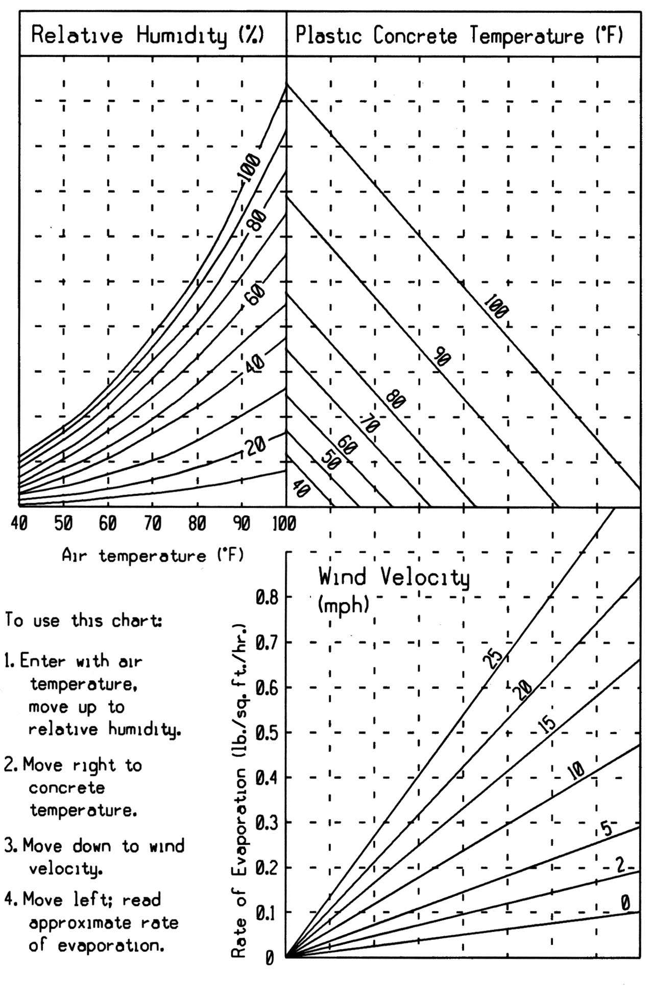
THEORETICAL RATE OF EVAPORATION CHART (English Units)
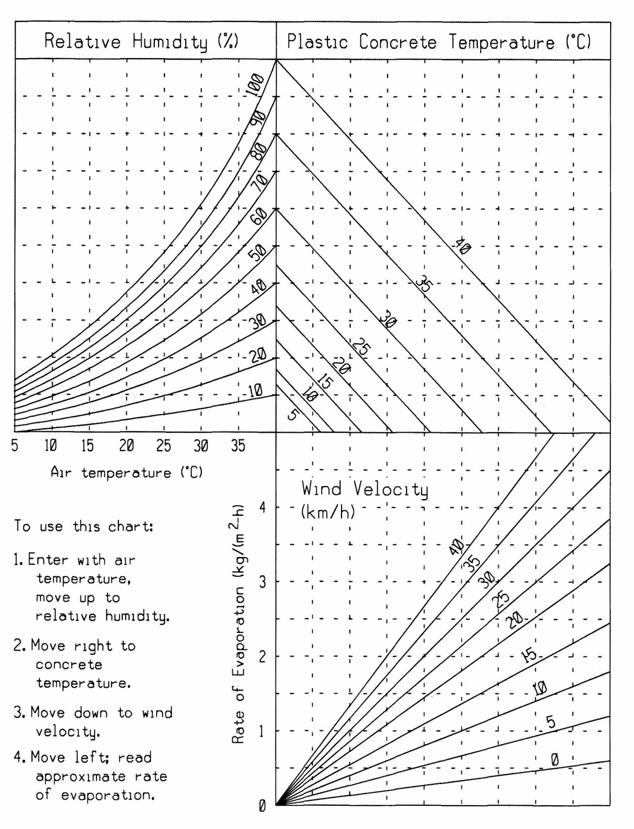
THEORETICAL RATE OF EVAPORATION CHART (Metric Units)
Section 2412. New Concrete Floors On Bridge Decks.
2412.01 DESCRIPTION.
This construction shall include all new concrete floors on timber, concrete, and steel
bridge decks. Sections 2403 and 2404
shall apply to this construction in addition to the following requirements.
When a two course construction with a second course of bridge floor surfacing or other wearing course, is specified, the requirements for the second course shall be as specified in Section 2413 or in the contract documents.
When an overlay for an existing floor, in conjunction with repair, is specified, the requirements for the overlay and repair shall be as specified in Section 2413 or in the contract documents.
2412.02 MATERIALS.
Materials used in concrete floors shall meet requirements for the respective materials
in Division 41.
Concrete used shall meet the requirements for C-4WR, C-L4WR, and C-V47B concrete mixtures, as specified in Materials I.M. 529. Coarse aggregate Gradation No. 3 or 5 of the Aggregate Gradation Table in Section 4109 shall be used. The fly ash and GGBFS shall meet the requirements of Section 4108. The maximum allowable substitution rates shall be as follows:
* Maximum total mineral admixture substitution shall be 50%.
Cement Type Maximum Allowable Substitution* Time Period Type I, Type II 35% GGBFS
20% Fly AshMarch 16 to October 15 Type IS, IP 0% GGBFS
20% Fly AshMarch 16 to October 15 Type I, II, IS, IP 0% GGBFS
0% Fly AshOctober 16 to March 15
Retarding admixture may be required by the contract documents or by the Engineer. A water reducing/retarding admixture meeting the requirements of Materials I.M. 403, Appendix B, shall be used in accordance with Section 2403. When placements require extended working times, the dosage rate shall be increased for the appropriate working time and temperature. For placements requiring normal working times, the dosage rate shall be in accordance with Section 4103. Other admixtures may be approved by the Engineer.
All retarding admixtures used shall be compatible with the air entraining agent used. Previous experience, satisfactory to the Engineer, will be required to indicate the approximate adjustments in proportions made necessary by the addition of the admixture and compatibility with other materials to be used. The retarding admixture shall be agitated prior to and during its use.Only one brand of cement shall be used during an individual placement. All aggregate shall be drained at least 24 hours after washing and before batching.
2412.03 SWINGING THE SPAN AND SUPPORT OF FORMS.
Before concrete is placed in the floor of a steel span, the centering of the span shall
be struck and the span swung free on its permanent supports. Unless otherwise specified
in the contract documents, forms for concrete floors and curbs shall be supported entirely
by the beams which are to support the concrete.
Temporary welds will not be authorized, unless otherwise approved by the Engineer, to attach hangers to steel beams to support floor form joists according to Article 2408.13. Galvanized hangers may remain exposed in the finished structure.
Welding on structural steel in the field will not be permitted, unless specified in the contract documents or approved by the Engineer.
2412.04 PLACING REINFORCEMENT.
All reinforcement shall be accurately placed in the positions shown in the contract
documents. Welding of reinforcing steel will not be permitted unless specified in the
contract documents or approved by the Engineer. In lieu of tying requirements in
Article 2404.06, reinforcement shall be tied rigidly
by wire at alternate intersections so that 50% of the intersections are tied. Steel
fabric reinforcement shall be of electrically welded rectangular mesh and shall be
in flat sheets.
Horizontal reinforcement shall be supported by an adequate number of supports as specified in Article 2404.07. The upper horizontal reinforcement shall be held securely in place by tiedowns 4 feet (1.2 m) apart, or the equivalent, which insure the reinforcement will not rise during concrete placement.
Concrete shall not be placed in a floor until the Engineer has inspected and approved the placing and fastening of the reinforcement. When checks indicate anticipated concrete cover over reinforcement is more or is less than specified in the contract documents, adjustments shall be made. If the lack of required concrete cover over reinforcement is due to over camber of the beams or improper elevation of beam splice points, the beam haunch shall be adjusted to provide proper cover while maintaining a smooth profile for the length of the floor. When the self propelled finishing machine described in Article 2412.06 is required, the elevation of upper reinforcement shall be checked using this machine, properly adjusted for finishing, with a suitable attached template adjusted to detect any reinforcement too close to the surface. The template shall be set to a tolerance of minus 1/4 inch (6 mm) to allow clearance of wire ties.
2412.05 PLACING CONCRETE.
The sequence in placing sections of concrete floors shall be as shown in the contract
documents or as modified by the Engineer. Placing of concrete floors when cold weather
protection is necessary will not be allowed without written permission of the Engineer.
Placing of concrete floors will not be allowed if the temperature of the plastic concrete at the time of placing exceeds 90�F (32�C). The Contractor has the option to cool the plastic concrete below 90�F (32�C) by a method approved by the Engineer at the Contractor's expense.
Placing concrete floors will not be allowed if the theoretical rate of evaporation for that day exceeds 0.2 lbs. per square foot per hour (1 kg/m2 per hour). The theoretical rate of evaporation shall be calculated using the Theoretical Rate of Evaporation Chart. The National Weather Service's maximum air temperature, relative humidity and maximum steady wind velocity without gusts, for the date and the location of the concrete floor placement, shall be used for this chart. The temperature of plastic concrete at time of placement shall be used for this chart.
THEORETICAL RATE OF EVAPORATION CHART (English Units)
THEORETICAL RATE OF EVAPORATION CHART (Metric Units)
2412.06 SURFACE FINISH.
Promptly after the concrete has been placed and vibrated as provided in
Articles 2403.08 and
2403.09, it shall be struck off with a template to provide a smooth surface
with the proper crown. Supports for the strike off template shall be parallel to
the center line of the structure, firmly fastened in place and set to the correct
elevation, with proper allowance for deflection caused by the load of the concrete.
These screed supports must extend sufficiently beyond each end of the bridge to
accommodate the strike off template or finishing machine used and to provide support
for bridges used when operating a longitudinal float. The Contractor may be required
to provide any or all of the items specified in Article
2301.07 which may be adapted to the work.
In lieu of the above requirements, for all bridges exceeding 60 feet (20 m) in length, the following shall apply:
Promptly after the concrete is deposited and vibrated, as provided in Articles 2403.08 and 2403.09, it shall be struck off to the proper elevation by means of an approved, self propelled and mechanically operated finishing machine. It shall operate on adequately supported rails adjusted to conform to the grade specified, with allowance for anticipated dead load deflection shown in the contract documents. Supporting rails shall extend beyond each end of the bridge a sufficient distance to accommodate the finishing machine. The load of the finishing machine shall not be so great as to cause undue deflection of the bridge members or falsework. The screeds of the finishing machine may be of metal or metal shod wood. Sufficient passes of the machine shall be made to obtain a void free surface struck off to the elevation specified. Finishing machines other than as described above will be considered for approval.
After the final pass of the finishing machine or after the floating operation, if used, the surface shall be smoothed to meet requirements of Article 2301.16 and checked with 10 foot (3 m) straightedges, and surface irregularities shall be corrected.
Promptly after smoothing and checking for smoothness and while the concrete is still plastic, the surface shall be given a final finish. When the contract documents show a second course of bridge floor surfacing or other wearing course, the surface of the first course shall be finished by a burlap drag. For one course bridge floors on Interstate and Primary projects, the final finished surface shall be smoothed and surface checked for smoothness without additional finishing.
A. Interstate and Primary Projects.
Transverse grooving or tining in the plastic concrete of the bridge deck (and bridge approaches when included in the bridge project) will not be allowed unless stated otherwise in the contract documents. Longitudinal grooves shall be cut into the hardened concrete surfaces using a mechanical cutting device. Longitudinal grooving shall be done after surface correction grinding.Longitudinal grooves shall be 1/8 inch +/- 1/64 inch (3 mm +/- 0.4 mm) in width, 1/8 inch +1/32 inch or -1/16 inch (3 mm +0.8 mm or -1.6 mm) in depth, and the grooves shall be uniformly spaced at 3/4 inch (19 mm) intervals measured center to center of groove.
Longitudinal grooving shall terminate approximately 6 inches (150 mm) from bridge joints. Longitudinal grooving on bridge decks and double reinforced bridge approach sections shall not be within the area closer than 1.5 feet (0.5 m) adjacent to curbs. To accommodate varying widths of grooving equipment, the width of the ungrooved area adjacent to curbs may be up to 3.0 feet (900 mm). Longitudinal grooving of single reinforced and non-reinforced bridge approach sections shall not be applied within 6 inches (150 mm) of the edge of outside lane lines.
For staged bridge and bridge approach construction, the Contractor may cut longitudinal grooves in the hardened concrete at the end of each stage of construction or wait until all stages have been completed. If the Contractor elects to delay cutting of the longitudinal grooves until completion of all stages, the concrete deck and bridge approach for any stage opened to traffic shall receive an interim coarse broom finish during placement. Within 30 calendar days following completion of the last stage of the project, the Contractor shall establish temporary lane closures to accomplish longitudinal grooving for all stages. The interim coarse broom finish will not be allowed as a surface texture when opened to traffic over a winter season. If the interim coarse broom texture is present and the Contractor is not in a position to finish all stages of the project, longitudinal grooving shall be cut into the hardened concrete in order to establish an acceptable driving surface texture for the winter season.
B. Other Projects.
When the surface being placed is the wearing course, the entire surface, except the area within approximately 2 feet (0.6 m) of the curbs, shall be given a suitable grooving by hand methods. Grooving shall be similar to that described in Article 2301.16, A, with the following exceptions:
- Grooving shall be transverse to the centerline of the roadway.
- Transverse grooving shall be randomly spaced from 3/4 inch to 1 5/8 inches (20 mm to 40 mm) with no more than 50% of the spacings exceeding 1 1/4 inches (30 mm) with a minimum of four different spacings in a 2 foot (0.6 m) width.
When the surface being placed is the final surface of a bridge sidewalk, the surface of sidewalk shall be given a transverse coarse broom texture.
Section 2428 shall apply to smoothness of the completed deck surface for Primary projects and when specifically required for other projects.
2412.07 CURING CONCRETE FLOORS.
Burlap prewetted with sufficient water, prior to placement, to prevent absorption of moisture
from the concrete surface shall be used. It shall be kept wet. The first layer of prewetted
burlap shall be placed in the following manner:
A. Interstate and Primary Projects.
The first layer of prewetted burlap shall be placed on the concrete within 10 minutes after final finishing.B. Other Projects.
Immediately after final finishing and grooving, the area finished shall be covered with white pigmented curing compound, meeting requirements of Article 4105.05, applied at a rate of not more than 135 square feet per gallon (3.3 square meters per liter). The first layer of prewetted burlap shall be placed on the concrete within 30 minutes after the concrete has been finished and grooved.
As soon as practical but not later than 2 hours after the first layer is placed, a second layer of burlap shall be placed on the floor. Water shall be applied to the burlap covering for a period of 4 calendar days by means of a pressure sprinkling system that is effective in keeping the burlap wet during the moist curing period. The system may be interrupted only to replenish the water supply, during periods of natural moisture, or during construction contiguous to the concrete being cured. Interruptions for periods longer than 4 hours may be approved by the Engineer on the basis of the method for keeping the concrete moist.
Continuous contact, except as noted above, shall be maintained between all parts of the concrete floor and the burlap during the 4 calendar day moist curing period.
On concrete floors placed after October 1 and prior to April 1, after 20 hours of the application of water, the Contractor may substitute the application of a moisture proof plastic film not less than 3.4 mils (86 �m) thick over the wet burlap in lieu of applying water. Intimate contact must be maintained between the surface of the concrete, the burlap, and the plastic film.
2412.08 CURBS.
Curbs and barrier railing shall be placed separately from the floor slab and in a manner
shown in the contract documents.
2412.09 JOINTS.
The location, type of filler, and details of expansion joints in concrete floors shall
be as shown in the contract documents. If steel expansion plates are required, the
Contractor for the superstructure shall furnish and install all such plates including
those required at the end of the bridge.
2412.10 FILLING AND SEALING JOINTS.
After removal of the strips of dummy filler, the concrete shall be allowed to harden
during the remainder of the cure period. When the joint is dry, it shall be cleaned and
completed. Filler and sealer shall meet requirements of Section
4136. When the type is not specifically designated, resilient filler shall be furnished.
A. When premolded filler is to be used, the filler shall be shaped to the proper cross section and placed in a manner that leaves a space at least 1/2 inch (15 mm) in depth in the joint from surface to filler. Space above the filler shall be sealed. Priming of joint edges may be required if recommended by the sealer manufacturer. Care shall be used to fill the space completely without smearing adjacent concrete. After the sealer has set, the surface may be lightly covered with Portland cement to prevent tracking from traffic.
B. When a preformed seal of the elastomeric compression type is required by the contract documents, the material shall be of the nominal dimensions shown, shall be a heavy duty type for bridge floor application, and shall have a rated capacity which will accommodate the joint movement. The Contractor shall submit for prior approval the name of the manufacturer and a description of the specific seal to be used. Fabricating shop details for steel armor shall conform to the manufacturer's recommended setting depth. The elastomeric compression seal shall be installed as follows:
The seal shall be installed by suitable hand or machine tools and thoroughly secured in place with lubricant adhesive which shall cover both sides of the seal over the full area in contact with the sides of the joint. Adhesive may be applied to the concrete or steel joints or to the seals or in combination. Seals shall be installed in a substantially fully compressed condition and, unless otherwise provided, shall be at least 1/4 inch (5 mm) and no more than 1/2 inch (15 mm) below the surface at all points.
For transverse joints across roadways, the seal shall be in one piece for the full width of the transverse joint. For longitudinal joints, the seal shall be provided in lengths as long as is practicable. All joints between lengths of seals shall be adequately sealed with additional adhesive.
Seals may be installed in concrete joints immediately after the curing period, using the lubricant-adhesive. Temperature limitations of the adhesive, as recommended by the manufacturer, shall be observed. Joints shall be clean, dry, and free of foreign material immediately prior to seal installation. Spalled surfaces in concrete joints shall be repaired to the satisfaction of the Engineer.
2412.11 METHOD OF MEASUREMENT AND BASIS OF PAYMENT.
Structural concrete, reinforcement, and structural steel will be measured and paid for
in accordance with Sections 2403, 2404,
and 2408, respectively. These payments shall be full compensation
for furnishing all materials, equipment, and labor and for performing all work necessary to
complete the structure in conformance with the contract documents.
When Section 2428 applies, payment may be modified as specified therein.
Deductions will not be made for the volume of concrete displaced by floor drains, expansion joints, shear lugs, beam flanges, and joint material. The cost of joint material and metal strips for sealing joints shall be included in the contract unit price per cubic yard (cubic meter) for structural concrete. The weight (mass) in pounds (kilograms) of structural steel paid for shall include all steel expansion plates, castings of steel or iron, welded shapes for floor drains, bearing plates, anchor bolts and other steel parts, except steel reinforcement for concrete and the metal fastenings therefor.
The cost of any additional concrete required to meet the requirements of Article 2412.04 shall be incidental to the cost of the structural concrete.
The quantity of Longitudinal Grooving in Concrete, in square yards (square meters), will be the plan quantity shown in the contract documents. The Contractor will be paid the contract unit price for longitudinal grooving in concrete per square yard (square meter).