SECTION 7010 - PORTLAND CEMENT CONCRETE PAVEMENT
Includes the requirements for the construction of full depth PCC pavement, curb and gutter, and overlays.
Follow the General Provisions (Requirements) and Covenants, as well as the following:
A.ĀĀ Two weeks prior to commencing any PCC pavement placement, submit a paving mix design for each different source of aggregate to be used for review and approval by the Engineer.Ā Submit mixes or mix designs approved by the Iowa Department of Transportation or an independent testing laboratory.
B.ĀĀ Maturity curves for paving mixes and maturity reading results.
C.ĀĀ Submit all testing and certifications according to Section 7010, 3.08.
Follow the General Provisions (Requirements) and Covenants.
1.05ĀĀĀĀĀ DELIVERY, STORAGE, HANDLING, AND SALVAGING
Follow the General Provisions (Requirements) and Covenants, as well as the following:
A.ĀĀ Aggregate Storage:Ā Comply with Iowa DOT Article 2301.02, C.
B.ĀĀ Cement and Fly Ash:Ā Comply with Iowa DOT Article 2301.02, C.
C.ĀĀ Admixtures:Ā Store in suitable weather tight enclosures which will preserve quality.
D.ĀĀ Reinforcing Steel: ĀStore off ground on timbers or other supports.
1.06ĀĀĀĀĀ SCHEDULING AND CONFLICTS
Follow the General Provisions (Requirements) and Covenants as well as the following:
Complete elements of the work that can affect line and grade in advance of other open cut construction unless noted on plans.
1.07ĀĀĀĀĀ SPECIAL REQUIREMENTS
None
1.08ĀĀĀĀĀ MEASUREMENT AND PAYMENT
1.ĀĀ Measurement:Ā Measurement will be in square yards for each different thickness of PCC pavement.Ā The area of manholes, intakes, or other fixtures in the pavement will not be deducted from the measured pavement area.
2.ĀĀ Payment:Ā Payment will be at the unit price per square yard for each thickness of PCC pavement.
3.ĀĀ Includes: ĀUnit price includes, but is not limited to, final trimming of subgrade or subbase, integral curb, bars and reinforcement, joints and sealing, surface curing and pavement protection, safety fencing, concrete for rigid headers, boxouts for fixtures, and pavement smoothness testing.
1.ĀĀ Measurement:Ā Measurement will be in square yards for each different thickness of PCC pavement subject to a unit price reduction for air content deficiency according to Section 7010, 3.08.
2.ĀĀ Payment:Ā Payment will be at the reduced unit price according to Table 7010.03 for each thickness of PCC pavement.Ā If there is an air content deficiency on a privately contracted roadway project, the Jurisdiction ultimately accepting ownership of the roadway will receive the penalty payment prior to acceptance of the work.
C.ĀĀ Pavement Smoothness Deficiency:
1.ĀĀ Measurement:Ā Measurement will be in square yards for each different thickness of PCC pavement subject to a unit price reduction for pavement smoothness according to Section 7010, 3.08.
2.ĀĀ Payment:Ā Payment will be at the reduced unit price according to Table 7010.04 for each thickness of PCC pavement.Ā If there is a pavement smoothness deficiency on a privately contracted roadway project, the Jurisdiction ultimately accepting ownership of the roadway will receive the penalty payment prior to acceptance of the work.
D.ĀĀ PCC Pavement Thickness Deficiency:
1.ĀĀ Measurement:Ā Measurement will be in square yards for each different thickness of PCC pavement that has deficient pavement thickness as determined in Table 7010.05.
2.ĀĀ Payment:Ā Payment will be at the percentage of the unit price indicated in Table 7010.05 for each different thickness of PCC pavement. ĀIf there is a pavement thickness deficiency on a privately contracted roadway project, the Jurisdiction ultimately accepting ownership of the roadway will receive the penalty payment prior to acceptance of the work.
1.ĀĀ Measurement:Ā Measurement will be in linear feet measured along the face of the curb for each different width and thickness of curb and gutter.
2.ĀĀ Payment:Ā Payment will be at the unit price per linear feet of curb and gutter.
3.ĀĀ Includes:Ā Unit price includes, but is not limited to, final subgrade/subbase preparation, bars and reinforcement, joints and sealing, surface curing and pavement protection, and boxouts for fixtures.
1.ĀĀ Measurement:Ā Measurement will be in linear feet measured along the face of the curb.
2.ĀĀ Payment:Ā Payment will be at the unit price per linear feet of beam curb.
3.ĀĀ Includes:Ā Unit price includes, but is not limited to, final subgrade/subbase preparation, bars and reinforcement, joints and sealing, surface curing and pavement protection, and boxouts for fixtures.
1.ĀĀ Measurement: ĀMeasurement will be in square yards of concrete median.Ā When the curb is integral with the pavement, the width will be measured from back of curb to back of curb.
2.ĀĀ Payment:Ā Payment will be at the unit price per square yard of concrete median.
3. Ā Includes:Ā Unit price includes, but is not limited to, final subgrade/subbase preparation, bars and reinforcement, joints and sealing, surface curing and pavement protection, and boxouts for fixtures.
H.ĀĀ Fixture Adjustment:Ā Comply with Section 6010 for adjustment of manholes and intakes and Section 5020 for adjustment of water valves and fire hydrants.
I.ĀĀĀ PCC Pavement Samples and Testing:
1.ĀĀ Measurement:Ā Lump sum item; no measurement will be made.
2.ĀĀ Payment:Ā Payment will be at the lump sum price for PCC pavement samples and testing.
3.ĀĀ Includes:Ā Lump sum price includes, but is not limited to, certified plant inspection, pavement thickness cores, profilograph pavement smoothness measurement (when required by the contract documents), and maturity testing.
J.ĀĀ Granular Surfacing:Ā Comply with Section 7030, Granular Driveway Surfacing, for granular surfacing material placed at intersecting roads, driveways, and turnouts.
1.ĀĀ Measurement:Ā Measurement will be in square yards for each different thickness of PCC pavement widening.Ā The area of manholes, intakes, or other fixtures in the pavement will not be deducted from the measured pavement widening area.
2.ĀĀ Payment:Ā Payment will be at the unit price per square yard for each thickness of PCC pavement widening.
3.ĀĀ Includes:Ā Unit price includes, but is not limited to, final subgrade/subbase preparation, integral curb, bars and reinforcement, joints and sealing, surface curing and pavement protection, safety fencing, concrete for rigid headers, boxouts for fixtures, and pavement smoothness.
1.ĀĀ PCC Overlay, Furnish Only:
a.ĀĀ Measurement:Ā Measurement will be in cubic yards of PCC furnished and incorporated for PCC overlay, including widening sections, partial depth patches, and irregular sections.
b.ĀĀ Payment:Ā Payment will be at the unit price per cubic yard of PCC furnished and incorporated for overlay.
c.ĀĀ Includes:Ā Unit price includes, but is not limited to, furnishing the concrete mixture and delivery to the project site.
2.ĀĀ PCC Overlay, Place Only:
a.ĀĀ Measurement:Ā Measurement will be
in square yards of PCC overlay placed, including
widening sections, partial depth patches, and irregular sections.Ā The area of
manholes, intakes, or other fixtures in the overlay will not be deducted from
the measured overlay area.
b.ĀĀ Payment:Ā Payment will be at the unit price per square yard of PCC overlay placed.
c.ĀĀ Includes:Ā Unit price includes, but is not limited to, integral curb, bars and reinforcement, joints and sealing, surface curing and pavement protection, safety fencing, concrete for rigid headers, boxouts for fixtures, and pavement smoothness testing.
3.ĀĀ Surface Preparation for Bonded PCC Overlay:
a.ĀĀ Measurement:Ā Measurement will be in square yards of pavement surface prepared for bonded PCC overlay.
b.ĀĀ Payment:Ā Payment will be at the unit price per square yard of pavement surface prepared for bonded PCC overlay.
c.ĀĀ Includes:Ā Unit price includes, but is not limited to, sandblasting, shot blasting, scarification, and surface cleaning.
4.ĀĀ Surface Preparation for Unbonded PCC Overlay:
a.ĀĀ Measurement:Ā Measurement will be in square yards of pavement scarified for unbonded PCC overlay.
b.ĀĀ Payment:Ā Payment will be at the unit price per square yard of pavement scarified for unbonded PCC overlay.
c.ĀĀ Includes:Ā Unit price includes, but is not limited to, scarification and surface cleaning.
5.ĀĀ HMA Stress Relief Course for Unbonded PCC Overlay:
a.ĀĀ Measurement:Ā Measurement will be in square yards of HMA stress relief course for unbonded PCC overlay.
b.ĀĀ Payment:Ā Payment will be at the unit price per square yard of HMA stress relief course for unbonded PCC overlay.
c.ĀĀ Includes:Ā Unit price includes, but is not limited to, HMA mix, including binder, and placement.
M.Ā Pavement Removal:Ā Comply with Section 7040.
A.ĀĀ Cement:Ā Meet the requirements of Iowa DOT Section 4101 and Materials I.M. 401, including Type I and Type II cements and blended hydraulic cements Type 1P, Type 1S, and Type 1L.
B.ĀĀ Supplementary Cementitious Materials (SCM):
1.ĀĀ Fly Ash:Ā Comply with Iowa DOT Section 4108.
2.ĀĀ Ground Granulated Blast Furnace Slag (GGBFS):Ā Comply with Iowa DOT Section 4108.
3.ĀĀ Limestone:Ā Comply with Iowa DOT Materials I.M. 401.
C.ĀĀ Fine Aggregate for Concrete:
1.ĀĀ Meet the requirements of Iowa DOT Section 4110 and Materials I.M. 409, Source Approvals for Aggregates.
2.ĀĀ Comply with the following gradation:
|
Sieve Size |
Percent Passing |
|
3/8ö |
100 |
|
No. 4 |
90 to 100 |
|
No. 8 |
70 to 100 |
|
No. 30 |
10 to 60 |
|
No. 200 |
0 to 1.5 |
|
Iowa DOT Article 4109.02, gradation No. 1. |
|
3.ĀĀ The Engineer may authorize a change in gradation, subject to materials available locally at the time of construction.
D.ĀĀ Coarse Aggregate for Concrete:
1.ĀĀ Crushed stone particles with Class 2 durability complying with Iowa DOT Section 4115 and Materials I.M. 409, Source Approvals for Aggregates.
2.ĀĀ Comply with one of the following gradations:
|
Sieve Size |
Gradation No. 3 Percent Passing |
Gradation No. 4 Percent Passing |
Gradation No. 5 Percent Passing |
|
1 1/2ö |
100 |
100 |
----- |
|
1ö |
95 to 100 |
50 to 100 |
100 |
|
3/4ö |
----- |
30 to 100 |
90 to 100 |
|
1/2ö |
25 to 60 |
20 to 75 |
----- |
|
3/8ö |
----- |
5 to 55 |
20 to 55 |
|
No. 4 |
0 to 10 |
0 to 10 |
0 to 10 |
|
No. 8 |
0 to 5 |
0 to 5 |
0 to 5 |
|
No. 200 |
0 to 1.5 |
0 to 1.5 |
0 to 1.5 |
|
Iowa DOT Article 4109.02, gradation No. 3, 4, and 5. |
|||
3.ĀĀ The Engineer may authorize a change in gradation, subject to materials available locally at the time of construction.
E.ĀĀ Water Requirements:Ā Comply with Iowa DOT Section 4102.Ā Potable water obtained from a municipal supply, suitable for drinking, may be accepted without testing.
F.ĀĀ Admixtures:Ā Meet the requirements for the liquid admixtures shown below.Ā Other admixtures may be used subject to the approval of the Engineer.
1.ĀĀ Air Entrainment Admixture:Ā Comply with Iowa DOT Section 4103.
2.ĀĀ Retarding and Water Reducing Admixtures:Ā Comply with Iowa DOT Section 4103.
3.ĀĀ Accelerating admixtures (calcium chloride):Ā Comply with Iowa DOT Article 2529.02.
G.ĀĀ Bars:Ā Comply with Iowa DOT Section 4151 for tie bars and dowel bars.Ā Meet the tie bar requirements for bar mats.Ā All bars must be epoxy coated.
H.ĀĀ Expansion Tubes:Ā Comply with Iowa DOT Section 4191.
I.ĀĀĀ Metal Keyways:Ā Comply with Iowa DOT Section 4191.
J.ĀĀ Supports for Bars:Ā Comply with Iowa DOT Materials I.M. 451.01.
K.ĀĀ Joint Fillers and Sealers:
1.ĀĀ Joint Sealers:Ā Comply with Iowa DOT Article 4136.02.
2.ĀĀ Preformed Expansion Joint Fillers and Sealers:Ā Use the following types of preformed materials for filling expansion joints that comply with Iowa DOT Article 4136.03.Ā When the type is not specified, use a resilient filler.
Ę Resilient filler
Ę Flexible foam expansion joint filler
Ę Tire buffings expansion joint filler
Ę Elastomeric joint seals
3.ĀĀ Backer Rod:Ā Comply with Iowa DOT Section 4136.
L.ĀĀ Liquid Curing Compound:Ā Comply with Iowa DOT Section 4105.
1.ĀĀ Burlap:Ā Comply with Iowa DOT Section 4104.
2.ĀĀ Plastic Film:Ā Comply with Iowa DOT Section 4106.
3.ĀĀ Insulating Cover:Ā Comply with Iowa DOT Section 4106.
N.ĀĀ Grout Systems:Ā Use polymer grouts that comply with Iowa DOT Materials I.M. 491.11.
1.ĀĀ Comply with Iowa DOT Class C or Class M mix meeting the requirements of Materials I.M. 529.
2.ĀĀ Ensure compatibility of all material combinations.Ā If the concrete materials are not producing a workable concrete mixture, a change in the material may be required.Ā Changes will be at no additional cost to the Contracting Authority.
B.ĀĀ Consistency and Workability:
1.ĀĀ Slump:
a.ĀĀ Use an amount of mixing water that will produce workable concrete of uniform consistency.Ā Unless specifically modified by the Engineer, ensure slump, measured according to Iowa DOT Materials I.M. 317, is no less than 1/2 inch or no more than 2 1/2 inches for machine finish and no less than 1/2 inch and no more than 4 inches for hand finish.
b.ĀĀ If it is not possible to produce concrete having the required consistency without exceeding the maximum allowable water to cement ratio specified, the cement content may be increased or water reducing admixture may be added.Ā Obtain the EngineerÆs approval.Ā Do not exceed the maximum water to cement ratio. ĀAdditional cement or water reducer will be added with no additional cost to the Contracting Authority.
c.ĀĀ The basic absolute volume of water per unit volume of concrete is based on average conditions.Ā If material characteristics require that the total quantity of water used to secure the required consistency reduces the batch yield (computed on the basis of absolute volumes of the batch quantities used) by more than 2.0%, the Engineer may adjust the proportions to correct the yield.Ā This adjustment will not be a basis for adjustment of the contract unit price.
2.ĀĀ Air Content:Ā Use an approved air entraining agent.
a.ĀĀ For machine-placed pavement, use a target air content of 8% with a tolerance of plus or minus 2% when measured on the grade just prior to consolidation, as determined by Iowa DOT Materials I.M. 318.Ā The target air content may be adjusted by the Engineer based on random tests of the consolidated concrete behind the paving machine.Ā These additional tests will be used to consider the need for a target value change and will not be used in the acceptance decision.
b.ĀĀ For hand-placed pavement, use a target content for hand finish of 7% with a tolerance of plus or minus 1.5% when measured on the grade and just prior to consolidation, as determined by Iowa DOT Materials I.M. 318.
C.ĀĀ Use of Fly Ash and Ground Granulated Blast Furnace Slag (GGBFS) as Supplementary Cementitious Materials:Ā Mix proportions for the various mixes using fly ash and GGBFS are included in Iowa DOT Materials I.M. 529.Ā The maximum allowable fly ash substitution rate is 20%.Ā Do not use a GGBFS substitution rate of more than 35% by weight (mass).Ā The total supplementary cementitious material substitution rate is not to exceed 40%.Ā When Type IP or IS cement is used in the concrete mixture, only fly ash substitution will be allowed.Ā Substitution of Type I/II cement with both GGBFS and fly ash will be allowed in ready mix concrete mixtures only.Ā Between October 16 and March 15, supplementary cementitious materials will be allowed only when maturity method is used to determine time of opening.Ā Transport, store, haul, and batch fly ash and GGBFS in such a manner to keep it dry.
Comply with Section 7010, 2.01 and 2.02, except as modified below:
1.ĀĀ Concrete Mix Design: ĀC-3WR or C-4WR for bonded overlays.
2.ĀĀ Aggregate: ĀComply with Iowa DOT Section 4115 and 4109, Gradation No. 3 and 5.
a.ĀĀ Use the same coarse aggregate type (crushed limestone or gravel) as the existing pavement as specified in the contract documents.
b.ĀĀ Use the maximum nominal coarse aggregate size that is no greater than one-third of the overlay thickness.
B.ĀĀ HMA Stress Relief Course for Unbonded PCC Overlays:
1.ĀĀ Asphalt Binder:Ā PG 58-28.
2.ĀĀ Mixture:Ā 300,000 ESAL, 3/8 inch mix, per Iowa DOT Section 2303.
a.ĀĀ Target air voids is 3%.
b.ĀĀ No maximum film thickness restriction.
c.ĀĀ No minimum filler/bitumen ratio restriction.
3.ĀĀ Aggregate:
a.ĀĀ Type B.
b.ĀĀ No percent crushed particle requirement.
c.ĀĀ Gradation cannot fall below the restricted zone.
A.ĀĀ Batching and Mixing Equipment:
1.ĀĀ General:
a.ĀĀ Weighing and Proportioning Equipment:Ā Comply with Iowa DOT Article 2001.20.
b.ĀĀ Mixing Equipment:Ā Comply with Iowa DOT Article 2001.21.
c.ĀĀ Material Bins:Ā Involves any structure in which materials are stored.Ā Each part of any bin, including foundations and supports, must be adequate to withstand any stress to which it might be subjected to while in use.
2.ĀĀ Batching:
a.ĀĀ Ensure the batching plant is Iowa DOT calibrated and approved.Ā Provide copy of current calibrations and approvals.
b.ĀĀ Coordinate the batch plant operation and batch trucks with the paving operation in order to ensure a steady supply of materials.
c.ĀĀ Operate the batch plant and trucks to minimize dust, noise, or truck nuisances.
3.ĀĀ Mixing:
a.ĀĀ Construction or Stationary Mixer:
1)ĀĀ Ensure the concrete is uniform in composition and consistency.Ā If this condition is not produced because of the size of the batch, the size of the batch may be reduced or the mixing time increased, or both, until this result is obtained.Ā If non-uniform, corrective action must be taken.
2)ĀĀ Ensure the methods of delivering and handling the concrete are such that objectionable segregation or damage to the concrete will not occur, and they will facilitate placing with a minimum of handling.
b.ĀĀ Ready Mixed Concrete:
1)ĀĀ Ensure the concrete is uniform in composition and consistency.Ā If non-uniform, concrete producers must take corrective action.
2)ĀĀ Ready mixed concrete is defined as concrete proportioned in a central plant and mixed in a stationary mixer for transportation in trucks without agitation, proportioned at a central plant, and only partially mixed in a stationary mixer for transportation and finish mixing in a transit mixer, or proportioned at a central plant, and then mixed in a transit mixer prior to or during transit.
3)ĀĀ When necessary to add additional mixing water at the site of placement, mix the batch at least an additional 30 revolutions of the drum at mixing speed.
4)ĀĀ Ensure each vehicle in which concrete will be delivered is capable of discharging concrete having a slump not over 2 inches at an overall rate for its entire load of not less than 1.25 cubic yards per minute.Ā Ensure the concrete is delivered at a rate sufficient to maintain a sustained rate of progress of not less than 100 feet per hour for the width and depth of pavement to be placed.
c.ĀĀ All Methods:Ā Identify each truck load by a plant charge ticket showing plant name, contractor, project data, quantity, class, time batched, and water added at site.
B.ĀĀ Concrete Placement Equipment:
1.ĀĀ Consolidating and Finishing Equipment:
a.ĀĀ Use a paving machine that meets all of the following:
1)ĀĀ Is designed for the specific purpose of placing, consolidating, and finishing concrete pavement.
2)ĀĀ Develops vertical edges on the pavement.
3)ĀĀ Is self propelled and equipped with a means for spreading the concrete to a uniform depth before it enters the throat.
4)ĀĀ Vibrates the concrete to the full width and depth being placed in a single passage.Ā Use vibrating tubes or arms working in the concrete or a vibrating pan operating on the surface of the concrete.
5)ĀĀ Produces a surface reasonably free of voids and tears.
6)ĀĀ When the paver is operated on previously placed concrete, prevent damage to the pavement surface.
7)ĀĀ For slip form pavers, use a paver equipped with automatic horizontal and vertical grade controls.
b.ĀĀ Hand methods utilizing air screeds and vibrating screeds may be used for short pavement runs, cul-de-sacs, driveways, and some intersections.
2.ĀĀ Vibrators for Machine Paving:
a.ĀĀ Consolidate, with a single pass of an approved internal or surface vibrator, the full width and depth of concrete requiring a finishing machine.Ā Operate internal vibrators within a frequency range of 4,000 to 8,000 vibrations per minute.Ā The Engineer may authorize the minimum vibration frequency to be lowered to 3,500 vibrations per minute for particular sections of paving, such as superelevations.Ā Operate surface vibrators within a frequency range of 3,500 to 6,000 vibrations per minute.
b.ĀĀ Avoid operating vibrators in a manner to cause a separation of the mix ingredients, either a downward displacement of large aggregate particles or an accumulation of laitance on the surface of the concrete.Ā When forward motion of the paver is reduced, vibrator frequency may need to be reduced to avoid separation of the mix.
c.ĀĀ If a vibrator fails to operate within the specifications, repair or change the vibrator before the paving begins:
Ę The following day, or
Ę The same day if the continuous paving that day is stopped at a header or at the end of a session.
d.ĀĀ If two adjacent vibrators fail to operate within the specifications, stop the paving operation and repair or replace the vibrators.
e.ĀĀ Stop vibrators whenever forward motion of the paver is stopped.
f.ĀĀĀ Set the internal vibrator penetration depth into the concrete pavement to mid slab or as deep as possible while passing above reinforcing steel.Ā Provide an operating position locking device so that no part of the vibrating unit can be lowered to the extent that it will come in contact with reinforcing steel or tie bars while paving.
g.ĀĀ Do not exceed the manufacturerÆs recommendations for vibrator horizontal spacing.Ā Do not exceed 16 inches from center to center.
h.ĀĀ Mount the longitudinal axis of the vibrator body approximately parallel to the direction of paving.Ā Tilt the trailing end of each vibrator downward to an approximate slope of 15 degrees below horizontal.
i.ĀĀĀ Use vibrators that meet or exceed the following specifications at the manufacturer's design frequency of 10,000 vpm:
1)ĀĀ Amplitude (peak to peak) 0.070 inches.
2)ĀĀ Centrifugal force 1,200 pounds.
3.ĀĀ Vibrators for Hand Methods:Ā Use a vibration rate between 3,500 to 6,000 vibrations per minute, and use an amplitude sufficient to be perceptible on the surface of the concrete more than 12 inches from the vibrating unit.
4.ĀĀ Hand Finishing Equipment:Ā Provide all finishing tools necessary for proper finishing of the concrete including straightedges for checking and correcting finished concrete surfaces.
5.ĀĀ Forms:
a.ĀĀ Rigid Forms:Ā Steel, minimum thickness of 5 gage, height at least equal to design thickness of pavement with base width at least 6 inches.
1)ĀĀ Minimum section length of 10 feet, joint connections designed to allow horizontal and vertical adjustment with locking device to hold abutting sections firmly in alignment.
2)ĀĀ Bracing, support, and staking must prevent deflection or movement of forms.
b.ĀĀ Flexible Forms:Ā Use steel or wood flexible forms for curves with a radius less than 100 feet.
1)ĀĀ Bracing, support, and staking must prevent deflection or movement of forms.
2)ĀĀ Ensure that forms used to shape back of curbs at returns have height at least equal to design thickness of pavement and curb height.
3)ĀĀ Forms must be free from scale and surface irregularities.
6.ĀĀ Curing Equipment:Ā Use pressure sprayer capable of applying a continuous uniform film of curing compound.Ā Use equipment with a shield if wind conditions do not allow proper coverage
7.ĀĀ Concrete Saws:Ā Use power operated concrete saws capable of cutting hardened concrete neatly.
8.ĀĀ Joint Sealing Equipment:Ā Use equipment capable of cleaning the joint and heating and installing sealant in joints according to manufacturer's recommendations.
3.02ĀĀĀĀĀ PAVEMENT CONSTRUCTION
A.ĀĀ Removal of Pavement:Ā Comply with Section 7040, 3.02.
B.ĀĀ Final Subgrade/Subbase Preparation:
1.ĀĀ General:
a.ĀĀ Meet the requirements of Section 2010 for subgrade construction, subgrade treatment, and subbase construction.
b.ĀĀ Trim the subgrade or subbase to the final grade for placement of concrete.
c.ĀĀ Unless otherwise ordered by the Engineer, the subgrade or subbase, at time of placing concrete for concrete pavement, must be in a uniformly moist but not muddy condition to a depth of not less than 1 inch.
2.ĀĀ Subgrade and Subbase Loading:
a.ĀĀ Travel of concrete delivery trucks on a subgrade or subbase must be approved by the Engineer.Ā In such cases, watering of the subgrade or subbase must be limited to just ahead of the paving machine.
b.ĀĀ Enter and exit from side streets to minimize repetitive loading on the subgrade or subbase by concrete trucks.
c.ĀĀ Do not allow loads in excess of the legal axle load on the completed subgrade or subbase.
d.ĀĀ Partially loaded trucks may be required.
e.ĀĀ If subgrade or subbase failure occurs, coordinate the repair with the Engineer.
3.ĀĀ Paving Suspended:
a.ĀĀ Suspend the paving operation where subgrade or subbase stability has been lost.
b.ĀĀ Do not place concrete on a subgrade or subbase that has become unstable, bears ruts or tire marks of equipment, or that is excessively softened by rain until such subgrade or subbase has been reconsolidated and reshaped to correct the objectionable condition.
c.ĀĀ If necessary, scarify to a minimum depth of 6 inches, aerating, and recompacting at no additional cost to the Contracting Authority.Ā Meet the compaction requirements of Section 2010, 3.06.
4.ĀĀ Maintenance of Subgrade or Subbase:Ā Maintain the completed subgrade or subbase during subsequent construction activities.
C.ĀĀ Surface Fixture Adjustment:
1.ĀĀ Adjust manhole frames and other fixtures within area to be paved to conform to finished surface.Ā Comply with Section 6010, 3.04 for manhole adjustments and Section 5020, 3.04 for water fixture adjustments.
2.ĀĀ Clean outside of fixture to depth of pavement before concrete placement.
3.ĀĀ Construct boxouts where allowed for later adjustment of fixtures.Ā See Figure 7010.103 for the size and shape of the boxout.
D.ĀĀ Setting of Forms:Ā When forms are used, meet the following requirements.
1.ĀĀ Ensure forms have sufficient strength to support paving operations being used.
2.ĀĀ Set base of forms at or below subgrade elevation with top of forms at pavement surface elevation.Ā With Engineer approval, extra height forms may be used to shape the back of integral curb and edge of pavement; set base at or below subgrade elevation with top of form at top of curb elevation.
3.ĀĀ Place and secure forms to required grade and alignment.Ā Do not vary the top face of the form from a true plane by more than 1/8 inch in 10 feet, and do not vary the vertical face from a true plane by more than 1/4 inch in 10 feet.
4.ĀĀ If the soil supporting the forms is softened by rain or standing water so that the forms are inadequately supported, or if voids occur under the forms, remove forms.Ā Rework subgrade to proper elevation and density, and reinstall forms.
5.ĀĀ Ensure forms are free of latent concrete and coated with release agent before concrete is placed.
E.ĀĀ Bar and Reinforcement Placement:Ā Ensure bars are clean, straight, free from distortion and rust, and are firmly secured in position as specified in the contract documents.Ā Place all bars in approved storage to prevent damage; do not distribute along the work site except as needed to avoid delay in paving.
1.ĀĀ Tie Bars:
a.ĀĀ Place bars prior to vibration.Ā Bars may be supported by approved chairs or may be placed in position by a machine or method approved by the Engineer.
b.ĀĀ Use approved continuous bolsters with runners to support reinforcement for bridge approach sections.Ā Place the supports transversely across the approach and space them longitudinally no greater than 4 feet.Ā For double reinforced approach sections the top layer of reinforcing may be chaired off the bottom layer of reinforcing using approved continuous high chairs with runners, provided they are positioned directly above the continuous bolsters with runners supporting the bottom layer of reinforcing. Hold epoxy coated reinforcing steel in place with epoxy or plastic coated bar supports and epoxy or plastic coated tie wires.
2.ĀĀ Dowel Bar Assemblies:
a.ĀĀ When dowel bar assemblies are required in the contract documents, accurately placeĀĀ ĀĀthese assemblies as shown.Ā To prevent their movement during subsequent concrete paving operations, securely stake or fasten to the base to line and grade.
b.ĀĀ Do not use assemblies that are damaged prior to placement.Ā If assemblies are damaged after placement, replace prior to paving.Ā Ensure horizontal and vertical alignment of the load transfer bars does not exceed 1/4 inch from parallel to line and grade.Ā Place each assembly so the bars are in a horizontal plane at T/2 ▒ 1/2 inch.
c.ĀĀ Check the placement of each assembly and the position of the bars within the assembly using a suitable template or other device approved by the Engineer.Ā If the assembly is found to be placed outside of the above tolerances, correct the placement.
d.ĀĀ Cutting the tie wires of the load transfer assemblies is optional.
3.ĀĀ Bar Mats for Reinforced Pavement:
a.ĀĀ When reinforced pavement is specified, assemble bar mats accordingly and firmly fastened together at all bar intersections.
b.ĀĀ Place, secure, latch, and tie bar mats for a continuous mat as specified in the contract documents.Ā Displacement during concrete placement operations is not allowed.
c.ĀĀ Use chairs to ensure proper placement of bar mats.
4.ĀĀ Tie Bars and Dowel Bars in Existing Pavement:
a.ĀĀ When anchoring in existing concrete, use a grout system according to the manufacturer's instructions.Ā Obtain the EngineerÆs approval for the grout system.
b.ĀĀ For horizontal installations, use either a pressure injection system with mechanical proportioning and mixing, or use encapsulated chemical anchors.Ā Install as follows:
1)ĀĀ Ensure drilled holes to receive the grout match the dimensions and spacing specified in the contract documents.Ā When not specified in the contract documents, the maximum nominal diameter of the hole must be 1/8 inch larger than the outside diameter of the dowel or bar, or as recommended by the manufacturer.Ā Drill holes for tie bars and dowel bars into the face of the existing pavement at midpoint.Ā To ensure proper horizontal alignment, do not allow any hole misalignments to exceed 1/4 inch in the vertical or horizontal plane.Ā Clean the hole with compressed air immediately prior to placing the grout.
2)ĀĀ Use a polymer grout to secure the dowels in the existing pavement.Ā Inject the grout into the rear of the hole with pressure.Ā Use sufficient grout so that when the bar to be grouted is placed in position, excess grout will be forced out the front of the hole.Ā Rotate the bar during the insertion process to ensure complete coating with the grouting material.Ā Hand proportioning and mixing is not allowed.
3)ĀĀ If using grout with approved encapsulated anchors, install according to the manufacturerÆs recommendations.
4)ĀĀ Use horizontal installation procedures for vertical or angled installations; however, pourable grouts may be used.Ā Pourable grouts must be mechanically mixed.
F.ĀĀ Concrete Pavement Placement:
1.ĀĀ Use paving machine for all uniform width pavements 8 1/2 feet or more in width and 250 feet or more in length, unless alternate methods are approved by the Engineer.Ā Screeds may be used on short pavement runs up to 250 feet.
2.ĀĀ Place, consolidate, and finish the concrete to the full depth and width conforming to the specified crown and cross-section in a single operation.
3.ĀĀ Keep a uniform pile of concrete in front of the paving machine, up to a maximum of 6 to 8 inches above the design surface elevation.Ā Distribute and spread the concrete as soon as placed.Ā A mechanical concrete spreader may be used.
4.ĀĀ Deposit the concrete upon the in-place bars keeping segregation to a minimum.
5.ĀĀ Use shovels, not rakes, to do necessary hand spreading and spading.
6.ĀĀ Do not allow the edges of pavement, including all longitudinal construction joints, to deviate from the line shown on the plans by more than 1/2 inch at any point.
7.ĀĀ If the paving machine operates on adjacent pavement, protect pavement from damage.
8.ĀĀ When placing by hand methods, consolidate the concrete by using vibrating units.Ā Use a definite system or pattern in the operation of the vibrator so the full width of concrete in each linear foot of lane will receive adequate and uniform consolidation.Ā The system and methods of vibrating is subject to approval of the Engineer.Ā Do not use vibrating equipment as a tool for moving concrete laterally.
G.ĀĀ Integral Curbs:Ā Integral curbs are placed with the pavement in a single paving machine operation; however, hand methods may be allowed for radius, returns, and sections of curb and gutter 100 feet or less in length or in other special sections where mechanical equipment cannot be used.
1.ĀĀ Pave, edge, protect, saw, and cure curb in same manner as pavement.
2.ĀĀ Finish curb as rapidly as finishing operations on pavement permit.Ā Maximum distance behind paving machine is 100 feet.
3.ĀĀ Complete final finish on curbs by hand methods, including the use of a 6 foot straightedge.
4.ĀĀ Check surfaces of curb and gutter with 10 foot straightedge; correct variations greater than 1/8 inch.
5.ĀĀ For drop curb at driveways and where sidewalks intersect streets, use forms to shape the backs of such curbs.
6.ĀĀ When using hand methods for building curb, the following additional requirements will apply:
a.ĀĀ Remove free water, latency, dust, leaves, or other foreign matter from the slab prior to placing concrete for curb.
b.ĀĀ Use freshly mixed concrete; do not store concrete in receptacles at side of pavement for use in curb at a later time; do not use concrete requiring retempering.
c.ĀĀ Consolidate curb concrete to obtain adequate bond with the pavement slab and to eliminate honeycomb in the curb.Ā Avoid disturbing the alignment of forms or the gutter flow line.
1.ĀĀ Grade and Crown:Ā Promptly after concrete has been placed and vibrated, strike off the surface to the true section by the screed.Ā Finish the surface true to crown and grade.
2.ĀĀ Watering the Surface:Ā The practice of lubricating the pavement surface by sprinkling water by spray, brush, or other methods to afford greater ease in finishing operation is not allowed.
3.ĀĀ Floats:Ā Finish surface with wood or magnesium floats; finish from both sides simultaneously if pavement is placed to full width with one pass of paving machine.
4.ĀĀ Straightedging:
a.ĀĀ After the longitudinal floating has been completed and the excess water has been removed, and while the concrete is still plastic, test the pavement surface for trueness.
b.ĀĀ Immediately fill any depressions found with freshly mixed concrete, struck off, consolidated, and refinished.
c.ĀĀ Check surface longitudinally while concrete is still plastic; correct any surface deviations greater than 1/8 inch in 10 feet.
5.ĀĀ Surface Treatment:
a.ĀĀ Drag Surface Treatment:Ā Unless otherwise specified, texture the finished surface with an artificial turf or burlap drag treatment.
1)ĀĀ Pull the artificial turf or burlap drag longitudinally over the finished surface to produce a tight, uniform, textured surface, and round the edges in a workmanlike manner.
2)ĀĀ Remove the artificial turf or burlap drag from the pavement surface at regular intervals and clean with water to remove accumulated concrete from the fabric in order to maintain a consistent finished texture.
3)ĀĀ When the desired texture is not attained, the Engineer may require the final finish be a broom finish.
b.ĀĀ Surface Tining:Ā When surface tining is specified, use a longitudinal tining.Ā Under special circumstances, when specified in the contract documents, transverse tining may be required.
1)ĀĀ Longitudinal:
a)ĀĀ Complete longitudinal surface tining using a machine with a wire broom or comb.Ā For small or irregular areas, or during equipment breakdown, hand methods may be used.Ā Use a broom or comb with a single row of tines 1/8 inch (+/- 1/64 inch) in width and uniformly spaced at 3/4 inch intervals.Ā The depth of the grooves must be a minimum of 1/8 inch to a maximum of 3/16 inch in the plastic concrete.
b)ĀĀ Use equipment with horizontal and vertical string line controls to ensure straight grooves.
c)ĀĀ Conduct this operation at such time and in such manner that the desired surface texture will be achieved while minimizing displacement of the larger aggregate particles and before the surface permanently sets.
d)ĀĀ At longitudinal joints, leave a 2 to 3 inch wide strip of pavement surface (centered along the joint) that is not grooved for the length of the joint.
2)ĀĀ Transverse:
a)ĀĀ If transverse surface tining is required or allowed, use a machine with a wire broom or comb.Ā For small or irregular areas, or during equipment breakdown, hand methods may be used.Ā Use a broom or comb with a single row of tines 1/8 inch (+/- 1/64 inch) in width and randomly spaced from 3/8 inch to 1 5/8 inch with no more than 50% of the spacing exceeding 1 inch.Ā The depth of the grooves must be a minimum of 1/8 inch to a maximum of approximately 3/16 inch in the plastic concrete.
b)ĀĀ Conduct this operation at such time and in such manner that the desired surface texture will be achieved while minimizing displacement of the larger aggregate particles and before the surface permanently sets.
c)ĀĀ Where abutting pavement is to be placed, the tining should extend as close to the edge as possible without damaging the edge.
d)ĀĀ If abutting pavement is not to be placed, do not tine the 6 inch area nearest the edge or 1 foot from the face of the curb.
6.ĀĀ Edge Finish:Ā Before the concrete has taken its initial set, finish all edges of the pavement with an 1/8 inch radius edging tool.
1.ĀĀ Apply liquid curing compound in a fine spray to form a continuous, uniform film on the horizontal surface and vertical edges of pavement, curbs, and back of curbs immediately after surface moisture has disappeared, but no later than 30 minutes after finishing.Ā With approval of the Engineer, the timing of cure application may be adjusted due to varying weather conditions and concrete mix properties to ensure acceptable macrotexture is achieved.
a.ĀĀ Use a white pigment liquid curing compound for concrete not receiving an asphalt overlay.Ā When specified in the contract documents, use a linseed oil solution.
b.ĀĀ Use a dark-colored curing compound for concrete receiving an asphalt overlay.
2.ĀĀ Apply compound with power sprayer; rate of application not less than 15 square yards per gallon (0.067 gallon per square yard); do not dilute compound.Ā For concrete receiving an asphalt overlay, use a minimum rate for dark-colored cure of 12.5 square yards per gallon (0.08 gallon per square yards).
3.ĀĀ Ensure liquid curing materials are well agitated in the supply drum or tank immediately before transfer to the sprayer.Ā Keep curing materials well agitated during application.
4.ĀĀ Hand operated sprayers may be used for small and irregular areas.
5.ĀĀ If forms are used, apply to pavement edges and back of curbs within 30 minutes after forms are removed.
6.ĀĀ If, due to other operations, the coating is damaged within 72 hours after being applied, immediately re-coat the affected areas.Ā Coating of the sawed surface with curing compound will not be allowed on joints that are to be sealed. When pavement is opened to traffic prior to 72 hours after application of the curing coating, a re-coating will not be required.
1.ĀĀ General:
a.ĀĀ Construct joints of the type, dimensions, and at the locations specified in the contract documents.Ā See the 7010 figures.
b.ĀĀ Place longitudinal joints coincident with or parallel to the pavement centerline.
c.ĀĀ Place all transverse joints at right angles to the centerline and extend the full width of the pavement.
d.ĀĀ Place all joints perpendicular to the finished grade of the pavement and do not allow the alignment across the joint to vary from a straight line by more than 1 inch.
e.ĀĀ Exercise care in placing, consolidating, and finishing the concrete at all joints.
2.ĀĀ Saw Joints:
a.ĀĀ Mark joint locations with a string line before sawing.
b.ĀĀ Begin transverse joint sawing as soon as the concrete has hardened sufficiently to allow sawing without raveling or moving of aggregate.Ā Saw joints before uncontrolled cracking takes place.
c.ĀĀ Saw all joints in a single cutting operation for a specific joint.Ā Make saw cuts true to line and to the dimensions specified in the contract documents.
d.ĀĀ Discontinue sawing a joint if a crack develops ahead of the saw.
e.ĀĀ Saw longitudinal joints within 24 hours of the concrete being placed.
f.ĀĀĀ If necessary, continue the sawing operations both day and night.
g.ĀĀ The concrete must be capable of supporting the sawing operations to allow the use of an early green concrete saw.
h.ĀĀ Repair or replace pavement with uncontrolled or random cracking at no additional cost to the Contracting Authority.Ā Use repair methods approved by the Engineer.Ā Repair or replace at the direction of the Engineer.
i.ĀĀĀ Use wet sawing for dust control when specified in the contract documents.
j.ĀĀĀ Where boxouts occur in pavement, construct joints as shown on Figures 7010.103 and 7010.904.
3.ĀĀ Construction Joints:
a.ĀĀ Place longitudinal and transverse construction joints where specified in the contract documents, at boxouts, and at headers.
b.ĀĀ Locate and place forms for boxouts on grade prior to paving as shown on Figures 7010.103 and 7010.904.
c.ĀĀ If concrete placement is delayed for more than 30 minutes or at the end of each day, construct a Days Work (DW) or a Rigid Tie (RT) transverse construction joint within 5 feet of a planned transverse contraction joint.
d.ĀĀ Finish the edges of the pavement at construction joints with a 1/8 inch radius edging tool.
4.ĀĀ Expansion Joints:
a.ĀĀ Install expansion joints as specified in the contract documents.
b.ĀĀ Prevent movement of or damage to joint assembly when placing concrete; set joint material low enough to clear the finish machine.
c.ĀĀ Construct double width expansion joint in curb over expansion joint in pavement.Ā The backside of the joint must be clear of concrete.
d.ĀĀ Align the expansion joint straight and true.Ā After the mechanical finishing equipment has passed over the joint, check the joint for movement.Ā If movement in excess of 1/2 inch has occurred, immediately correct the installation to its intended position.
e.ĀĀ If joint fillers are assembled in sections, or if joints as a whole are constructed in sections, do not allow offsets between adjacent fillers.
f.ĀĀĀ Where more than one section is used in a joint, securely lace or clip the sections together.
g.ĀĀ Supplemental vibration equipment is required for proper consolidation of the concrete.
h.ĀĀ After the surface finishing has been completed, finish the edge of the joint with a 1/8 inch edging tool.
1.ĀĀ Timing:
a.ĀĀ Unless otherwise allowed or approved by the Engineer, before any portion of the pavement is opened to the Contractor's equipment or to general traffic, clean and seal joints that require sealing.
b.ĀĀ The Engineer may limit the wheel loads and axle loads of equipment operating on the pavement during this operation, if prior to the age and strength specified in Section 7010, 3.07.Ā Additional tests to determine the pavement strength may be required.
2.ĀĀ Cleaning:
a.ĀĀ For those joints that are not to be sealed, cleaning is not required.
b.ĀĀ Within 3 hours after a joint has been wet sawed to the finished dimension, flush the wet sawing residue away from the sawed faces using a high pressure water blast operating with a minimum pressure of 1,000 pounds per square inch.Ā Within 3 hours after a joint has been dry sawed to the finished dimension, blow the dry sawing residue from the joint using air compressors that provide moisture and oil free compressed air.
c.ĀĀ Immediately prior to installation of sealant, clean joints with an air blast.Ā Do not perform sealing until visual examination verifies the joint surfaces appear dry, in addition to being clear of dust and contamination.
3.ĀĀ Sealing:
a.ĀĀ Prepare and install joint sealer in the joint and to the proper level specified in the contract documents and as recommended by the manufacturer.
b.ĀĀ Heat hot-poured sealers in a thermostatically controlled heating kettle; heat the material to the temperature required for use, but not above that recommended by the manufacturer.Ā After sealing, remove excess sealer from the pavement surface.
c.ĀĀ Seal joints the same day they are cleaned.Ā Apply sealant only when the joint surfaces appear dry by visual examination.
d.ĀĀ Place joint sealer only when the pavement and ambient air temperatures are 40░F or above.Ā When near this minimum, additional air blasting or drying time, or both, may be necessary to ensure a satisfactory bond to the joint faces.Ā When this sealer cannot be properly placed due to late fall work, submit a joint construction plan and sealing details to the Engineer for approval before commencing paving.Ā Delay the cleaning, sealing, and, if required, resawing of joints until the following spring.Ā This delay requires the EngineerÆs approval.
e.ĀĀ When surface correction is required, repair seals damaged from the corrective work.Ā Joint preparation, cleaning, and sealing may be delayed until after corrective work, provided the pavement is not opened to traffic before corrective work is performed.
L.ĀĀ Pavement Backfill:Ā Following slipform paving operations, place backfill material along the pavement within 48 hours of pavement attaining opening strength or as directed by the Engineer to prevent flow of water and any subsequent damage caused by undermining of the pavement.Ā Prior to placement of full backfill material, construct check dams or other protection as appropriate to ensure no damage to the subgrade and/or subbase occurs.
1.ĀĀ Timing:
a.ĀĀ Remove forms after the initial set of the concrete has taken place.
b.ĀĀ Remove stakes and forms with care to prevent cracking, spalling, or over stressing concrete.Ā If damage does occur, repairs will be made as required by the Engineer.
2.ĀĀ Honeycomb Repair:
a.ĀĀ When the forms are removed, fill honeycombs with mortar composed of 1 part cement and 2 parts fine aggregate by weight.
b.ĀĀ If the honeycombing is to the degree and nature that it is considered by the Engineer as defective work, remove and replace at no additional cost to the Contracting Authority.
3.ĀĀ Paving Protection:Ā In the area adjacent to the curbs and pavement edge, immediately place backfill after the forms are removed.Ā Construct dams or other protection to ensure that no saturation or erosion of the subgrade under or near the pavement occurs.Ā This may include check dams, pumping, etc.
3.03ĀĀĀĀĀ CURB AND GUTTER CONSTRUCTION (See Figure 7010.102)
A.ĀĀ Complete the construction of curb and gutter separate from pavement in the same manner as for pavement in Section 7010, 3.02.
B.ĀĀ Use a paving machine for curb and gutter.Ā For curb and gutter sections less than 250 feet, hand finish methods may be used.
3.04ĀĀĀĀĀ OVERLAY CONSTRUCTION
Construct overlays in the same manner as PCC pavement, except as modified herein.
1.ĀĀ Surface Preparation:
a.ĀĀ Over PCC:
1)ĀĀ Remove dirt, oil, foreign material, or concrete laitance from existing pavement surface by shot blasting or sandblasting.
2)ĀĀ Scarify to a nominal depth of 1/4 inch.
3)ĀĀ Sweep and air blast surface to remove any loose dirt or debris.Ā Keep air blasting operations as close to overlay operations as possible to prevent any resettlement of debris onto previously cleaned area.
b.ĀĀ Over HMA:
1)ĀĀ Scarify to the depth specified in the contract documents, but no less than 1/4 inch.Ā Trim high spots in the existing asphalt surface at the direction of the Engineer.
2)ĀĀ Sweep and air blast surface to remove any loose dirt or debris.Ā Keep air blasting operations as close to overlay operations as possible to prevent any resettlement of debris onto previously cleaned area.
2.ĀĀ Placing and Finishing:
a.ĀĀ Surface Condition:Ā Ensure the prepared surface is dry to allow some absorption of the concrete mortar.
b.ĀĀ Jointing:
1)ĀĀ Over PCC:Ā Use a reliable method to mark the location of all joints to be matched.
a)ĀĀ Longitudinal:Ā Saw directly over existing joints full depth.
b)ĀĀ Transverse:Ā Saw directly over existing joints full depth of the overlay plus 0.5 inches.
2)ĀĀ Over HMA:
a)ĀĀ Longitudinal:Ā Saw to a depth of one third the overlay thickness.
b)ĀĀ Transverse:Ā Saw to a depth of one fourth the overlay thickness with a conventional saw or no less than 1.25 inches with an early entry saw.
c.ĀĀ Curing:Ā Apply cure material at twice the normal rate of application.
d.ĀĀ Restrictions:
1)ĀĀ Air Temperature:Ā Do not place overlay concrete when air or existing pavement surface is below 40░F.
2)ĀĀ Pavement Temperature:Ā Do not place overlay on HMA when the pavement surface temperature exceeds 120░F.Ā If the surface of the HMA is above 110░F, the Contractor may apply water to the surface of the HMA ahead of the paving operation in order to cool the surface. Apply water far enough in advance of the paving operation so that the surface will dry from evaporation before concrete is placed. Do not apply water to the surface of the pavement when the HMA surface temperature is below 100░F.
3)ĀĀ Time of Year:Ā Do not place bonded overlays from October 1 to May 31.
1.ĀĀ Surface Preparation:Ā Clean the existing pavement surface immediately prior to paving to remove dirt or debris.Ā Trim high spots in the existing asphalt surface as specified in the contract documents.Ā Do not scarify the existing PCC surface if an HMA stress relief course will be constructed.
2.ĀĀ Placing and Finishing:
a.ĀĀ Surface Condition:Ā Ensure the prepared surface is dry to allow some absorption of the concrete mortar.
b.ĀĀ HMA Stress Relief Course:Ā Place HMA stress relief course over existing PCC pavement when specified in the contract documents.Ā Ensure a minimum compaction of 94% of laboratory density for the HMA layer.Ā Use static steel wheeled rollers only.
c.ĀĀ Jointing:
1)ĀĀ Longitudinal:Ā Saw to a depth of one third the overlay thickness.
2)ĀĀ Transverse:Ā Saw to a depth of one fourth the overlay thickness with a conventional saw or no less than 1.25 inches with an early entry saw.
d.ĀĀ Curing:Ā Apply cure material at twice the normal application rate.
e.ĀĀ Restrictions:
1)ĀĀ Air Temperature:Ā Do not place concrete overlay when air or existing pavement surface is below 40░F.
2)ĀĀ Pavement Temperature:Ā Do not place overlay on HMA when the pavement surface temperature exceeds 120░F.Ā If the surface of the HMA is above 110░F, the Contractor may apply water to the surface of the HMA ahead of the paving operation in order to cool the surface. Apply water far enough in advance of the paving operation so that the surface will dry from evaporation before concrete is placed. Do not apply water to the surface of the pavement when the HMA surface temperature is below 100░F.
A.ĀĀ Weather Conditions:Ā Do not place concrete when stormy or inclement weather or temperature prevents good workmanship. ĀTemperature restrictions and protection requirements may be modified by the Engineer under unusual conditions.
1.ĀĀ Cold Weather:
a.ĀĀ Paving:Ā Do not place aggregates containing frozen lumps, and do not place concrete on a frozen subgrade or subbase.Ā Take all necessary actions to prevent the pavement from freezing.
1)ĀĀ Concrete mixing and placement may be started, if weather conditions are favorable, when the air temperature is at least 34║F and rising.Ā At the time of placement, concrete must have a temperature of at least 40║F.
2)ĀĀ Stop mixing and placing when the air temperature is 38║F or less and falling or if the temperature stops rising and does not reach 38║F.
b.ĀĀ Protection:Ā Prior to applying protection, cure all concrete pavement and curb/gutters, including exposed edges of the pavement and curb.Ā In addition, protect concrete less than 36 hours old as follows:
|
Night Temperature Forecast |
Type of Protection1 |
|
35░F to 32░F |
One layer of burlap for concrete. |
|
31░F to 25░F |
Two layers of burlap or one layer of plastic on one layer of burlap. |
|
Below 25░F |
Four layers of burlap between layers of 4 mil plastic or equivalent commercial insulating material approved by the Engineer. |
|
1Ā Keep protection in place until one of the following conditions is met: a.Ā The pavement is 5 calendar days old. b.Ā Opening strength is attained. c.Ā Forecasted low temperatures exceed 35░F for the next 48 hours. d.Ā Forecasted high temperatures exceed 55░F for the next 24 hours and subgrade temperatures are above 40░F. |
|
1)ĀĀ Shut down paving operations in time to comply with protection requirements outlined above.Ā During cold weather, allow more time for finishing and protection.Ā Perform all finishing and covering operations prior to darkness.Ā Temperature restrictions and protection requirements may be modified by the Engineer.
2)ĀĀ Equivalent commercial insulating material approved by the Engineer may be used.Ā This material must be waterproof and have a minimum R value of 1.0.Ā If initial set has not yet occurred, place a layer of burlap on top of concrete prior to placing insulating blankets.
3)ĀĀ Use a method of protection and materials that will maintain the concrete temperature above 40░F.
2.ĀĀ Hot Weather:Ā Hot weather condition is defined as any combination of the following conditions that tend to impair the quality of plastic concrete by accelerating the rate of moisture loss and rate of cement hydration causing thermal shrinkage and resulting in plastic shrinkage cracking:
Ę High Ambient Temperature
Ę High Concrete Temperature
Ę Low Relative Humidity
Ę High Wind Velocity
Ę Solar Radiation
a.ĀĀ General:
1)ĀĀ During hot weather conditions, the Engineer may restrict concrete placement to early morning or evening hours.
2)ĀĀ During hot weather conditions, advise the Engineer of the results of the theoretical evaporation rate throughout paving operations.
b.ĀĀ Determine the Theoretical Rate of Evaporation:Ā Use the following chart and the National Weather ServiceÆs predicted maximum air temperature, relative humidity, and maximum steady wind velocity without gusts, for the date and the location of the paving pour.
|
Theoretical Rate of Evaporation Chart |
|
|
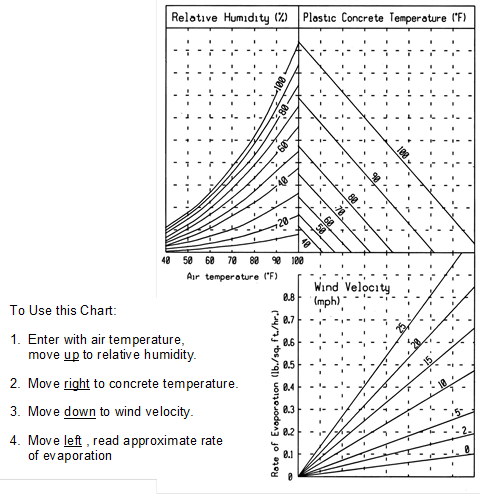
c.ĀĀĀ If the evaporation rate exceeds 0.1 pounds per square foot per hour but is less than 0.3 pounds per square foot per hour, provide the following concrete evaporation protection.
1)ĀĀ Immediately apply an approved evaporation retarder to the concrete pavement and curbs or increase the surface cure application to 1.5 times the standard specified rate.
2)ĀĀ Take special precautions to ensure that the forms and subgrade are sufficiently moist or protected to avoid lowering the water content at the pavement/subgrade interface.Ā In hot weather conditions, moisten the subgrade the evening before operations.
3)ĀĀ Ensure that the time between placing and curing is minimized and eliminate delays.
4)ĀĀ Moisten concrete aggregates that are dry and absorptive.
5)ĀĀ Use a fog spray to raise the relative humidity of the ambient air if there is a delay in immediately applying the curing compound.
6)ĀĀ Minimize solar heat by shading, wetting, or covering concrete chutes or other equipment that comes in contact with plastic concrete.
d.ĀĀ If the evaporation rate is 0.3 pounds per square foot per hour or greater, discontinue placement of concrete.
3.ĀĀ Rain Protection:
a.ĀĀ Have materials available, near the work site, for proper protection of the edges and surface of concrete.Ā Protective material may consist of sheets of burlap or plastic film.Ā Also have planks or other material with suitable stakes that can be used as temporary forms available.
b.ĀĀ If initial set has not occurred, take every precaution necessary to protect the surface texture of the concrete.
c.ĀĀ If so determined by the Engineer, failure to properly protect concrete will constitute cause for removal and replacement of defective pavement.
B.ĀĀ Night Conditions:Ā Perform all finishing and covering operations prior to darkness (half an hour after sunset).Ā Do not commence construction until half an hour before sunrise.Ā Do not place or finish concrete under artificial light, unless approved by the Engineer.
1.ĀĀ General:
a.ĀĀ Protect the new pavement and its appurtenances from traffic, both public and that caused by the ContractorÆs own employees and agents, at no additional cost to the Contracting Authority.Ā This includes the erection and maintenance of warning signs, lights, barricades, watchmen to direct traffic, and pavement bridges or crossovers.
b.ĀĀ Do not operate equipment with metal tracks, metal bucket blades, or metal motor patrol blades directly on new paving.Ā Do not unload soil or granular materials, including base rock for storage and future reloading directly onto new paving.
2.ĀĀ End of DayÆs Run:
a.ĀĀ At the end of each day's run and at all side streets, erect and maintain safety barriers and fencing as necessary to protect the pavement from damage.
b.ĀĀ Install safety fences within 1 hour of the completion of finishing and curing operations.Ā Leave fences in place and maintained until the concrete has attained the minimum strength or age.
c.ĀĀ Intermediate safety fences may be required for the purpose of opening the pavement for access to a side road, side street, or entrance.
3.ĀĀ Repair of Damages:Ā At the discretion of the Engineer, and at no additional cost to the Contracting Authority, repair or replace any part of the pavement damaged by traffic or other causes occurring prior to final acceptance of the pavement.
Time for opening pavement for use is determined by maturity method complying with Iowa DOT Materials I.M. 383 or age and test results.Ā The minimum age and test results needed for opening are shown in Table 7010.01.
3.07ĀĀĀĀĀ TRANSPORTATION RESTRICTIONS
A.ĀĀ Do not use concrete transported with continuous agitation when the cement has been in contact with the aggregate more than 90 minutes before it is placed.Ā With the approval of the Engineer, an approved retarding admixture may be used at the rates required in Iowa DOT Materials I.M. 403.
B.ĀĀ Do not use concrete transported without continuous agitation if the period elapsed between the time the concrete is mixed and the time it is placed is greater than 30 minutes.Ā With the approval of the Engineer, an approved retarding admixture may be used at the rates required in Iowa DOT Materials I.M. 403 and the mixed-to-placed time may be extended.
C.ĀĀ Ensure the methods of delivering and handling the concrete are such that objectionable segregation or damage to the concrete will not occur, and concrete placing will occur with a minimum of rehandling.
D.ĀĀ Thoroughly clean the truck compartment in which concrete is transported and flush with water to ensure that hardened concrete will not accumulate.Ā Discharge the flushing water from the truck compartment to the designated discharge point before it is charged with the next batch.
A.ĀĀ Testing:Ā Provide the following material certifications and testing required to be performed by Supplier or Contractor.
|
Table 7010.02:Ā Material Certifications and Testing
|
|||||
|
Material or Construction Item |
Tests |
Applicable Standard1 |
Methods of Acceptance of Sampling and Testing |
Field Sampling and Testing |
|
|
Frequency (minimum) |
Responsible Party |
||||
|
Fine Aggregates |
Gradation |
Cert. Plant Insp.2 |
1/250 CY or min 1/day |
Supplier/ Contractor |
|
|
Moisture |
Cert. Plant Insp.2 |
1 per 1/2 day |
|||
|
Specific Gravity |
Cert. Plant Insp.2 |
1/250 CY or min 1/day |
|||
|
Quality |
Approved Source |
Prior to use |
|||
|
Coarse Aggregates |
Gradation |
Cert. Plant Insp.2 |
1/250 CY or min 1/day |
||
|
Moisture |
Cert. Plant Insp.2 |
1 per 1/2 day |
|||
|
Specific Gravity |
Cert. Plant Insp.2 |
1/250 CY or min 1/day |
|||
|
Quality |
Approved Source |
Prior to use |
|||
|
Portland Cement |
Quality |
Approved Source |
Prior to use |
||
|
Fly Ash |
Quality |
Approved Source |
Prior to use |
||
|
GGBFS |
Quality |
Approved Source |
Prior to use |
||
|
Curing Compound |
Quality |
Approved Source |
Prior to use |
||
|
Joint Sealer |
Quality |
Approved Source |
Prior to use |
||
|
Epoxy Dowel Bars and Assemblies |
Quality |
Approved Source |
Prior to use |
||
|
Tie Bars |
Quality |
Approved Source |
Prior to use |
||
|
Plastic Concrete |
Air Content |
Field Test |
1/200 CY or min. 1/day |
Engineer |
|
|
Slump |
Field Test |
1/200 CY or min. 1/day |
|||
|
Cylinders 6" |
Field Test |
Set of 3/500 CY or two sets/day |
|||
|
Beams |
Field Test |
Set of 3/500 CY or two sets/day |
|||
|
Thickness |
------------ |
Field Test |
1/200 CY |
||
|
Hardened Concrete |
Smoothness |
Field Test - Straightedge |
Project length |
||
|
Smoothness |
Field Test - Profilograph |
Project length |
Contractor |
||
|
Thickness |
Field Test |
1 core/1000 SY or 3 cores/project |
|||
|
Strength |
Maturity Tests3 |
Prior to placement |
|||
|
1Ā Refers to the Iowa DOT Materials I.M.s, Iowa DOT Standard Specifications, or SUDAS Standard Specifications. |
|||||
|
2Ā Certified plant inspection per Iowa DOT Materials I.M. 527. |
|||||
|
3Ā The Contractor is responsible for developing the maturity curve for the specified mix, taking maturity readings, and delivering a copy of the results to the Engineer. |
|||||
1.ĀĀ Air content of the concrete will be evaluated according to Iowa DOT Materials I.M. 318 and 327.
2.ĀĀ When a test result is outside the tolerance for the target air content, the contractor will be notified immediately.Ā An air test will then be immediately run behind the paver to aid in identifying the limits of the non-complying air.Ā A test result between 5% and 8% behind the paver will be considered complying.Ā This test will represent all concrete from the back of the paver back to the last documented complying test.Ā Make immediate adjustments to the mix production and placement process to bring the air content back within tolerance.Ā Do not use succeeding loads below the lower target air content tolerance by more than 0.5%.Ā Each subsequent load will be tested until air content is within tolerance for two consecutive loads.Ā For all incorporated, non-complying concrete that is out of tolerance, the Engineer will determine if removal and replacement is required or if a price adjustment, according to Table 7010.03, will be applied.
C.ĀĀ Pavement Smoothness:Ā Evaluate pavement smoothness for all PCC pavement and overlay surfaces.
1.ĀĀ Straightedge:Ā The Engineer will check PCC pavement surfaces with a 10 foot straightedge placed parallel to the centerline.Ā Areas showing high spots of more than 1/4 of an inch in 10 feet will be marked.Ā Complete surface corrections according to the procedures in Iowa DOT Section 2316 to an elevation where the area or spot will not show surface deviations in excess of 1/8 inch when tested with a 10 foot straightedge.Ā Surface corrections will be completed at the direction of the Engineer with no additional cost to the Contracting Authority.
2.ĀĀ Profilograph:
a.ĀĀ If specified in the contract documents, comply with Iowa DOT Section 2316 to measure pavement smoothness with a profilograph.
b.ĀĀ Evaluate according to the smoothness requirements of Table 7010.04 and make surface corrections and price reductions.Ā Surface corrections will be completed with no additional cost to the Contracting Authority.Ā No incentive for pavement smoothness will be made.
|
Table 7010.04:Ā Pay Factor if Profilograph Used
|
|
|
Segment Index (inch/mile) |
Pay Factor |
|
0 - 22.0 |
100% |
|
22.1 - 30.0 |
97% |
|
30.1 and over |
Grind as directed by Engineer |
c.ĀĀ Smoothness measurements will be suspended for structures and through intersections.
1.ĀĀ At locations determined by the Engineer, cut samples from the pavement by drilling with a core bit that will provide samples with a 4 inch outside diameter.Ā Restore the surface by tamping low slump concrete into the hole, finishing, and texturing.Ā The Engineer will witness the core drilling, identify, and take possession of the cores.Ā The Engineer will determine the core locations, measure the cores, and determine the thickness index according to Iowa DOT Materials I.M. 346 and 347, except as modified as follows:
a.ĀĀ For regular or irregular shaped areas, use a lot size of 1,000 square yards.Ā Include remnants less than 500 square yards in the last lot and remnants greater than 500 square yards in a separate lot.Ā Take a minimum of three cores per project.
b.ĀĀ For any core with a deficiency greater than 0.15 inch, take two additional cores in that pavement lot and use the average of the three cores.
2.ĀĀ Coring of pavement or other work for thickness determination may be waived by mutual agreement for sections of the same design thickness less than 2,500 square yards.
3.ĀĀ Based on the thickness index determined by the Engineer, the pavement payment will be as shown in Tables 7010.05 and 7010.06.
4.ĀĀ If the thickness index deficiency is greater than 0.51 for pavements thinner than 9 inches or 0.91 for pavements 9 inches or thicker, the Engineer will study the extent and severity of the deficiency of the pavement areas.Ā The Engineer will require one of the following based on a review on the level of deficiency, the amount of the payment penalty, and the estimated reduction in the design life of the deficient pavement:
a.ĀĀ Removal and replacement of the deficient areas with pavement complying with the contract documents at no additional cost to the Contracting Authority.
b.ĀĀ Completion of an agreement that provides a combination of an extended guarantee period and payment penalty and allows the deficient pavement to be left in place.
E.ĀĀ Defects or Deficiencies:Ā Remove and replace or repair pavement containing excessive cracks, fractures, spalls, or other defects at no additional cost to the Contracting Authority.Ā The method of replacement or repair will be determined by the Engineer.
END OF SECTION