ESTIMATE OF PORTLAND CEMENT CONCRETE
STRENGTH BY MATURITY METHOD
GENERAL
This IM outlines the procedure for using the maturity concept as a nondestructive method to estimate concrete strength.
Determination of concrete maturity (time temperature factor (TTF)) and estimating in place concrete strength is a two-step procedure as follows:
- Maturity Curve - A relationship must be established between the maturity (TTF) and the concrete strength as measured by destructive methods (that is, through testing of beams or cylinders). The development of the maturity-strength curve shall be done at the plant site at the beginning of construction using project materials and the project proportioning and mixing equipment.
- Field Maturity - The second step is the temperature monitoring of the placed concrete. Temperature probes are installed in the concrete and the temperature is measured. From those measurements, along with the age at which the measurements were taken, the maturity (TTF) is calculated and used to estimate the concrete strength. A maturity meter may also be used to determine the maturity value (TTF).
For concrete furnished from a construction or stationary mixer, which is in place prior to construction of the specified project, a maturity curve may be established ahead of actual construction of the specified project. The test specimens shall be cast with concrete made from the same plant and using the same materials source as will be used in the specified project. The agency shall be informed and have an opportunity to observe the development of the maturity curve and validation.
THE MATURITY CONCEPT
The hydration of cement and gain in strength of the concrete is dependent on both curing time and temperature. Thus, the strength of the concrete may be expressed as some function of time and temperature. This information can then be used to determine the strength of concrete without conducting physical tests. The time-temperature function commonly used is the maturity concept proposed by Nurse-Saul (ASTM C1074),
M (oC x hours) = ∑ [(T – T0) ∆t]
Where M is the maturity in oC-hours [M is also termed the time-temperature factor (TTF)], Δt is the time interval in hours (or days), T is the average concrete temperature during the time interval Δt, and T0 is the datum temperature at which concrete ceases to gain strength with time. The value of T0 = 14oF (-10oC) is most commonly used. As a result, Equation 1 becomes:
M (oC x hours) = ∑ [(T + 10) Δt] Equation 2
EQUIPMENT
· 12 - 6 in. x 6 in. x 20 in. (152 mm x 152 mm x 508 mm) beam molds
· 1 each shovel (square point), rubber hammer or equivalent, and wood float or equivalent
· Hydraulic testing machine – center point loading flexural
· Maturity meter – a device that automatically measures, records, and displays the maturity (TTF) value
· Hand-held thermometer - a temperature measuring device with a thermocouple wire or probes readable to the nearest 0.1°C and accurate to 1°C.
· Temperature data logger – a device that measures temperature and electronically stores the readings a minimum of once per hour
ESTABLISHMENT OF MATURITY-STRENGTH RELATIONSHIP - MATURITY CURVE
To establish a maturity-strength relationship for a concrete mix, a maturity meter and a hydraulic testing machine are needed. The following procedure shall be used: (NOTE: Before using any maturity meter, check to be sure the datum temperature is set to -10ºC.)
1. Cast a minimum of twelve (12) 6 in. x 6 in. x 20 in. (152 mm x 152 mm x 508 mm) beams, as per IM 328. Test the entrained air content and slump of the concrete being used to cast the beams, as per IM 327. Record these values. The concrete shall meet specifications, with a minimum air content of 5.5%. Since there is a direct relationship between w/c ratio and strength, the concrete used to develop the maturity-strength relationship shall be at the maximum w/c ratio expected during production. The beams shall be cast from a batch of at least 3m³ (3 cu. yd.).
2. Embed a thermocouple wire near each end of a test beam (when flexural strength is to be determined) to monitor the temperature. This beam will be the last to be tested. A probe shall be inserted near each beam end to the approximate mid-depth and such that they are approximately 3 in. (75 mm) from each side and each end. Loop the wire around the beam box handles to prevent the wire from being inadvertently pulled out of the beam. The average of the two readings will be used in the development of the maturity-strength curve. A maturity meter shall be used to develop the curve. A temperature data logger may be used to develop the curve and the maturity (TTF) shall be calculated from hourly readings.
3. Cast, cure, and test the beams at the plant site. Test strength in accordance to IM 316. This will allow a maturity meter to be protected from the weather and theft. The meter can be stored in a lab trailer or vehicle with the probes run outside to the beam in the sandpit. The beams shall be covered with plastic immediately after casting and prior to form removal. If possible, wet burlap should be placed over the surface of the beams under the plastic. The forms shall be removed the following day. All beams shall be cured, buried in a pit of wet sand after form removal, until they are tested. Beams may be cured in a saturated lime tank, only if the water temperature is controlled at 60 to 80 °F (16 to 27°C).
Precaution: When the concrete temperature is below 50°F (10°C), maturity strength development will cause over extended maturity (TTF) values. Development of strength maturity relationship should be performed on concrete with temperatures above 50°F (10°C).
When air temperatures are expected to fall below 40°F (4°C), place the beams on a piece of foam board or plywood to prevent the cold ground from lowering beam temperatures. Placing insulation over the beams to retain heat may also be warranted.
4. Determine maturity (TTF) and strength values at four different ages. Test three specimens for strength at each age and calculate the average strength at each age. The maturity (TTF) value shall be calculated from a temperature reading at the time the specimen is tested for strength. The tests shall be spaced such that they are performed at somewhat consistent intervals of time and span a range in strength that includes the opening strength desired. Ideally, there would be at least two sets of strength values below the opening strength. For Class C or QMC mixtures, the first set of beams will typically be tested at an age of approximately 12 to 16 hours, depending on concrete temperature. Test age may need to be increased when concrete temperature is below approximately 50 °F (10°C) or decreased at higher temperatures above approximately 85 °F (29°C). The average strength of the first set of beams must be less than 425 psi (2.93 MPa) for the curve to be valid.
If the maturity curve is intended for use in determining the time to begin joint sawing, additional test specimens will need to be cast and strength testing must begin at lower maturity values.
For pavements, a minimum flexural strength of 3.45 MPa (500 psi) is required for opening. (See Article 2301.03) For structural concrete, a minimum flexural strength of 3.95 MPa (575 psi) is required before concrete may be subjected to flexural loading. Strength requirements vary for determining when forms for roofs of culverts may be removed (See Article 2403.18). Testing intervals may need to be increased over those for paving. For structures, if design compressive strength is desired, develop a maturity curve utilizing cylinders for compressive strength. Ensure the last set of cylinders is above the design strength by testing at 3, 7, 14, and 28 days (or earlier if already above design strength).
5. Plot the measured strength against the corresponding values of maturity at different ages, as determined by the maturity meter or by hand methods. Use the spreadsheet provided by the District Materials Concrete Technician to determine maturity-strength relationship. The maturity (TTF) value corresponding to the required opening strength shall be used to determine when the pavement or structure may be loaded. An example of the Maturity-Strength Development form, generated by the computer program, is included at the end of this IM. This form shall be reviewed by the DME. Copies will be provided to the Project Engineer, DME, Concrete Materials Engineer, and the contractor.
FIELD MATURITY (TTF) PROCEDURE – Estimate in place concrete strength
Placement of the Temperature Probes
Strip the coating from each end of the two wires and twist the ends together before inserting them into the fresh concrete.
Pavements
For pavements, insert the temperature probe into the concrete until the end is at approximately the pavement mid-depth and 1.6 feet (0.5 m) from the edge of the pavement. The wire ends are the points at which the temperature measurement is taken. Insertion may be accomplished by attaching the wire ends to a wooden dowel and embedding it into the slab. Check to ensure the concrete is consolidated around the dowel. The portion of the dowel that protrudes above the pavement should be cut or broken off after the testing is completed.
Probes may be placed at any point along the pavement slab. A minimum of two probes shall be placed in each day's placement with one at the end of the days run. On days when there is a large difference between daytime high temperatures and nighttime low temperatures, placing additional probes near the beginning of the day's run and at a point near the midday location provides useful information. The concrete placed during the middle of the day can gain strength faster than the concrete placed at the beginning of the day because of daytime heating. Place probes at side roads, or other locations, where opening to traffic is critical.
Structures
For structures, a minimum of two probes shall be attached to the reinforcing steel near the edge at the upper corner of the exposed surface. (See Figure 1 at the end of this IM.) The probe should be wrapped around the rebar and taped with approximately 1 to 2 inches (25 to 50 mm) extending below the rebar to prevent the probe from damage and removal during concrete placement. The rebar should also be taped 2 to 3 inches (50 to 75 mm) on both sides of the probe location to prevent contact with the reinforcing steel. (See Figure 2 at the end of this IM.)
Temperature Data Collection and Maturity (TTF) Calculation
Handheld thermometers (Pavements)
Typically, a handheld thermometer is used to collect temperature readings for pavements. The probe wire ends, extending out from the concrete, may be connected to a plug. A plug with thermocouple wires and clips attached to the handheld thermometer may also be used to connect to the wires extending from the concrete. Be careful to connect the copper wire to the copper plug prong (+).
Once the wires are placed, an initial temperature of the concrete shall be taken and recorded. Temperature readings should be taken in the morning and late afternoon as a minimum for standard A, B and C mixtures. For the fast-setting mixtures, readings should be taken every few hours, depending on weather conditions and mixture.
A Maturity Data Recording Sheet, provided at the end of this IM, may be used to record the temperature readings and calculate the maturity values.
A temperature data logger is required for monitoring structures. The maturity value shall be calculated based on hourly readings obtained from the device. The device may also be used for monitoring pavements.
If a maturity meter is being used to monitor either pavements or structures, it should be connected to the probe as soon as possible to begin data collection. The maturity (TTF) value may be read directly from the maturity meter. Some maturity meters are not moisture proof and will be permanently damaged if not protected from water or moisture.
A Level I PCC technician shall place probes, perform all calculations, and submit forms to the Engineer. The Level I PCC technician may supervise other personnel to obtain temperature readings or read maturity values.
Implementation
For pavements, it is the intent of the procedure to use the maturity method to open the pavement to traffic from the very first day of paving, including the days of development of new curves.
Pavement placed on the first day during development of the strength-maturity curve may be opened when either of the following criteria has been met:
1. The TTF of the slab meets or exceed the opening TTF as determined by the strength-maturity curve being developed.
1. At a particular test age, the average strength of the three beams used for development of the strength-maturity curve meets or exceeds the required opening strength.
For structures, since maturity is to be used on units exposed to flexural loading, the maturity curve should be developed early in the project during placement of concrete exposed to compressive stress. If this is not possible, concrete placed on the same day as development of the strength-maturity curve may be loaded at a particular age using either of the first day placement criteria required for pavements.
Curve Validation
A curve validation is required once every 30 calendar days during normal plant production. If the plant has not supplied concrete to the project for a period of greater than 30 days, the curve must be validated prior to continued use The validation tests shall be conducted to determine if concrete strength is being represented by the current maturity curve. Cast and cure three (3) beams using the same procedure and manner as used to develop the current maturity curve. Test all three beams as close as possible to the maturity value determined to represent the opening strength of the pavement or the flexural loading strength or form removal strength of the structure.
Pavements
For pavements, if the average calculated strength value at the TTF the validation beams were tested is within the range of ±50 psi (0.34 MPa) of the original curve, the original curve shall be considered validated.
Structures
For structures, if the average calculated strength is greater than the original curve at the TTF the validation beams were tested, the original curve shall be considered validated.
An example of the Validation of the Maturity Curve is included at the end of this IM. Copies shall be provided to the RCE, DME, and the contractor.
This validation procedure is a check to ensure the mix is basically the same as originally tested. If the test results indicate a new curve must be developed, this should be done in a timely manner. The curve currently being used shall be continued until new beams can be cast and at that point the implementation procedure described above shall be followed.
Factors Requiring a New Curve
Changes in material sources, proportions, and mixing equipment all affect the maturity value of a given concrete mixture. Development of a new maturity curve due to material source or proportion changes in a concrete mix may be waived by use of the validation procedure.
The following will require a new curve to be developed:
· The validation beams tested meet either of the following conditions:
- For pavements, the average calculated strength at the TTF tested is below the minimum range (-50 psi (-0.34 MPa)) of the original maturity curve.
- For structures, the average calculated strength at the TTF tested is lower than the original maturity curve.
· The w/c ratio of the production concrete exceeds the w/c ratio of the concrete used to develop the strength-maturity curve by more than 0.02.
Maturity Meter Calibration
Maturity meters shall be calibrated yearly to ensure proper temperature sensing. The calibration may be performed at the Central Laboratory, before the start of each construction season. To ensure accurate temperature measurement, the maturity meter should also be checked periodically against a certified thermometer or other calibrated meter. Some maturity meters may need to be sent to the manufacturer for calibration.


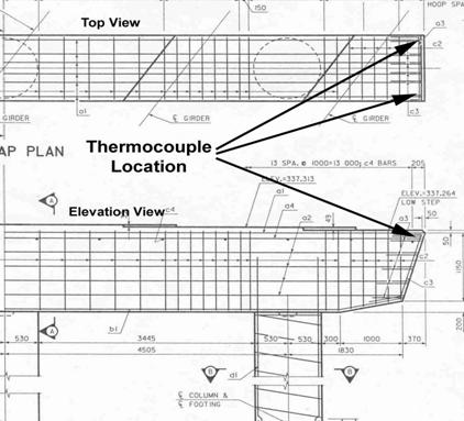
Figure 1. Typical thermocouple location placement in pier cap
Use similar method for thermocouple placement in other structural elements.
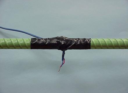
Figure 2. Typical attachment of thermocouple to reinforcing steel