GENERAL REQUIREMENTS
The welding qualification requirements for fabrication and/or repair of any aluminum sign support structures for highway signs, light poles and traffic signals shall be in accordance with the requirements of the Structural Welding Code – Aluminum AWS D1.2/D1.2M: 2003, Aluminum Welding Code for Class III Structures and the requirements of Article 2423 of the standard specifications.
WELDING PROCESS
All welding shall be done by the following process:
GMAW - Gas Metal Arc Welding
Other processes may be approved by the Engineer.
BASE METAL
Base Metal shall conform to ASTM B221, Alloy Group 6061-T6.
PROCEDURE QUALIFICATION
A Welding Procedure Specification (WPS) shall be required and shall be submitted for approval. WPS shall be prepared in accordance with Section 3 and Annex E of the AWS D1.2 Structural Welding Code.
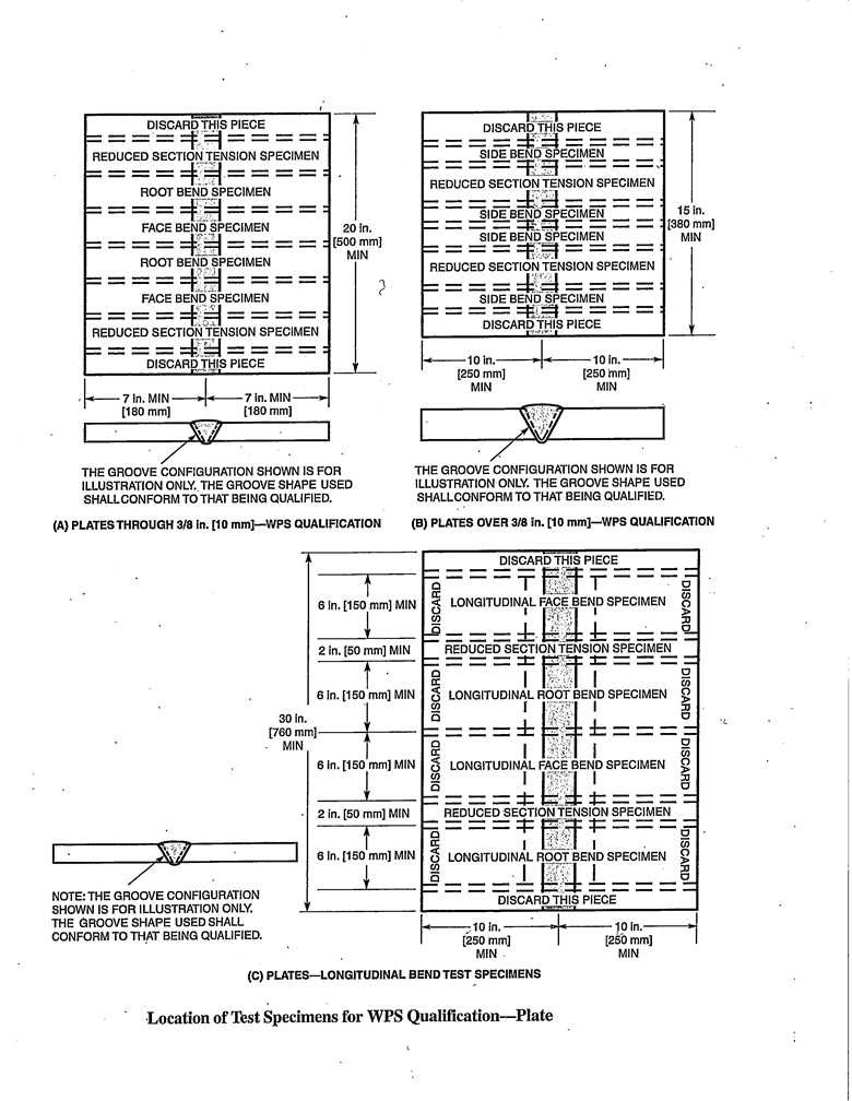
Qualification of the WPS shall be in accordance with Section 3, Part C using the Base Metal, Procedure Qualification Record (PQR), joint preparation, surface preparation, cleaning and limiting variables from Part C, Section 3.14 of the AWS D1.2 Structural Welding Code.
ELECTRODES
Electrodes shall be of the type specified on the plans or in the AWS D1.2/D1.2M: 2003 as listed in Table 4.2. Certificate of Conformation shall be required and shall be submitted for review and verification.
ACCEPTANCE CRITERIA – GROOVE WELDS PLATE & PIPE (AWS D1.2, 3.6.2)
The visual examination of the test weldment shall satisfy the following acceptance criteria:
- Both the face and the root surfaces shall be free of cracks.
- All craters shall be filled to the full cross section of the weld.
- The edges of the weld shall blend smoothly with the base metal.
- Underfill shall not exceed 0.01”
- The root shall show:
- Complete fusion for CJP groove welds.
- Penetration equal to or greater than the weld size specified for PJP groove welds.
- The maximum melt through on groove welds in pipe or in tubing shall not exceed 1/8” (3 mm).
- The root cavity shall not exceed 1/16”.
- Total weld thickness shall be equal to or greater than the thickness of the base metal but the weld reinforcement shall not exceed the following values:
|
Thickness |
Maximum Reinforcement |
|
inch |
inch |
|
t ≤ 3/8 |
3/32 |
|
3/8 < t ≤ 3/4 |
1/8 |
|
t > 3/4 |
3/16 |
note: The above indicated values for a given plate thickness joint welded from both sides.
|
Thickness |
Maximum Reinforcement |
|
inch |
inch |
|
t ≤ 1/4 |
3/23 |
|
1/4 < t ≤ 1/2 |
1/8 |
|
1/2 < t ≤ 1 |
5/32 |
|
t > 1 |
3/16 |
note: The above indicated values for a given plate thickness joint welded from one side.
The tensile and yield strength for temper T6, Alloy 6061 shall be as follows: 38 Ksi (Tensile),
When fracture occurs in the weld metal, a minus 5% tolerance shall be allowed, if fracture occurs outside the weld metal.
ACCEPTANCE CRITERIA – FILLET WELDS FOR PLATE AND PIPE (AWS D1.2, 3.6.3)
The visual examination of the test weldment shall satisfy the following acceptance criteria:
- Surface of the welds shall be free from any cracks.
- All craters shall be filled to the full cross section of the weld.
- The edges of the weld shall blend smoothly with the base metal.
- Underfill shall not exceed 0.01”.
- The weld shall exhibit complete fusion in the root and to the base metal by the macroetech test.
- The leg length shall meet the requirements of the WPS.
- Root surface concavity (suck-back) shall not exceed 1/32”.
GROOVE WELDS – PLATE, PIPE AND CASTINGS
- Visual examination of the test weldment shall conform to the requirements of Part B Section 3.6 of the AWS D1.2/D1.2M: 2003.
- Note: Macroetching of the cut sections shall be included in the examination of fillet welds and PJP Groove Welds.
- Tension test specimens shall conform to the requirements of Part B, Section 3.7 of the D1.2 AWS Code.
- Bend test specimens shall conform to the requirements of Part B, Section 3.8 of the D1.2 AWS Code.
- Soundness Test Castings shall conform to the requirements of Part B, Section 3.9 of the D1.2 AWS Code.
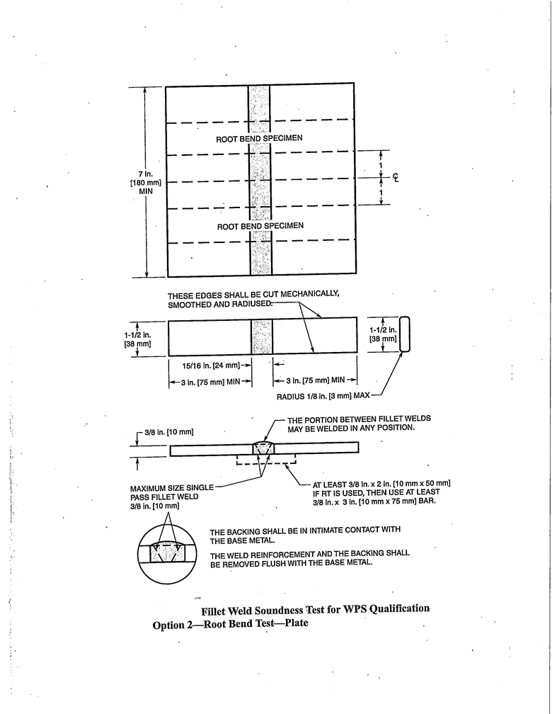
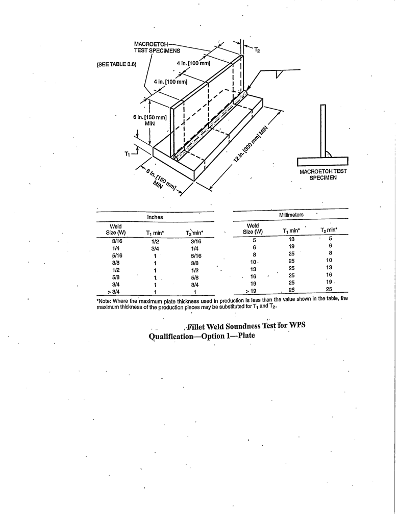
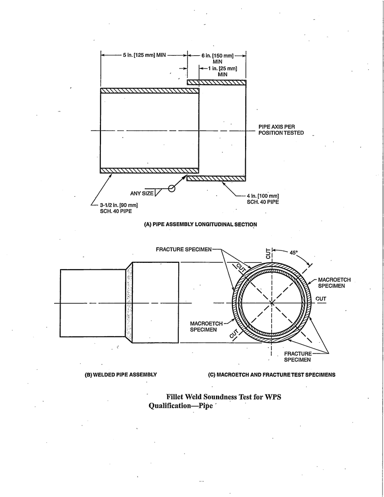
- Soundness Tests Fillet Welds for Plates and Pipes shall conform to the requirements of Part B, Section 3.10 Option 1 (Fillet Weld Fracture Test – Pipe and Plate), and Option 2 (Fillet Weld Root Bend Test – Plate).
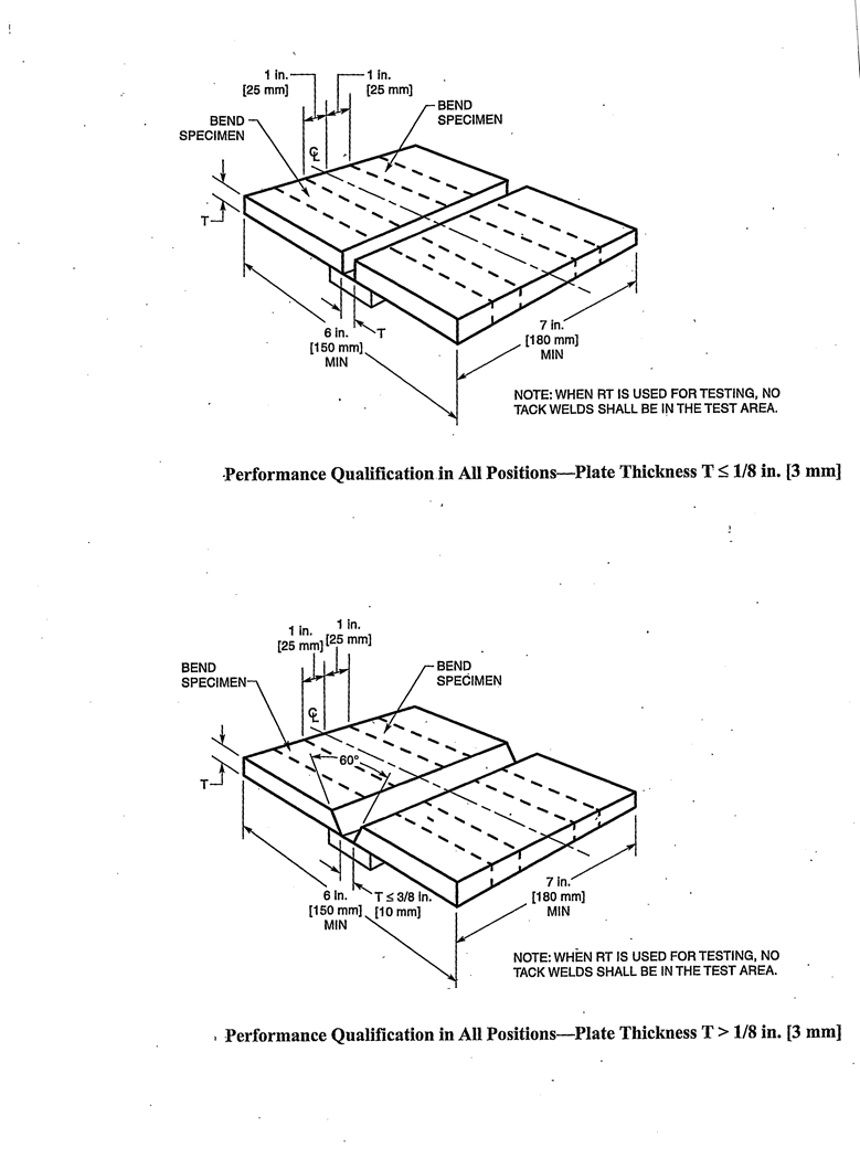
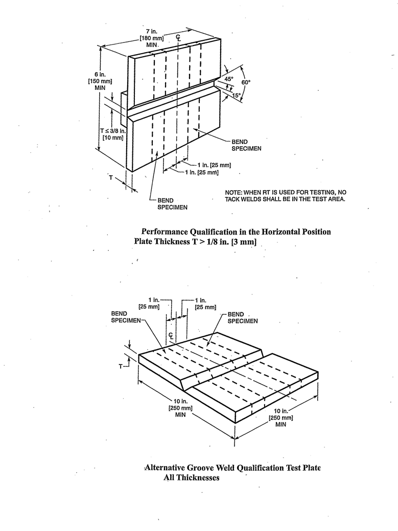
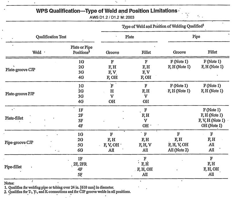
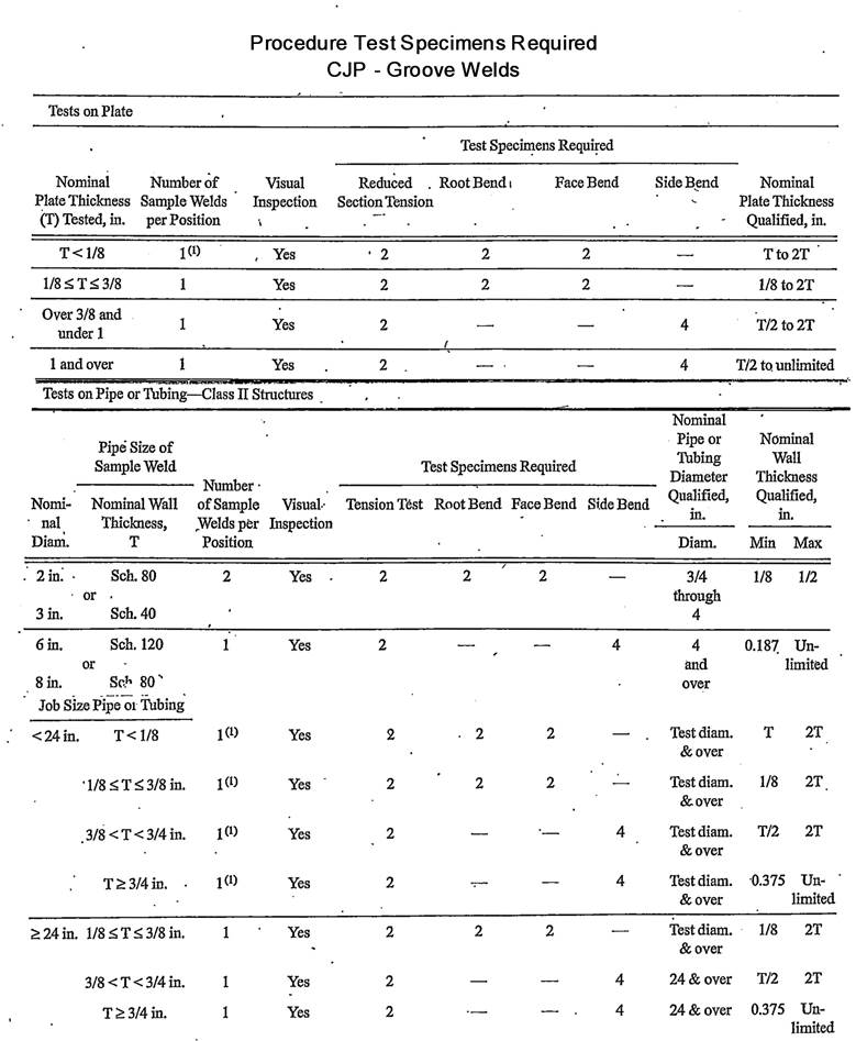
POSITION AND TESTS FOR PROCEDURE WELDS
Each WPS shall be qualified by positioning and welding test plates as follows:
Note: These positions are classified as (1) Flat, (2) Horizontal, (3) Vertical, or (4) Overhead
Note: Plate – Groove – 1G (Flat), 2G (Horizontal), 3G (Vertical), 4G (Overhead)
Plate – Fillet – 1F (Flat) 2F (Horizontal), 3F (Vertical), 4F (Overhead)
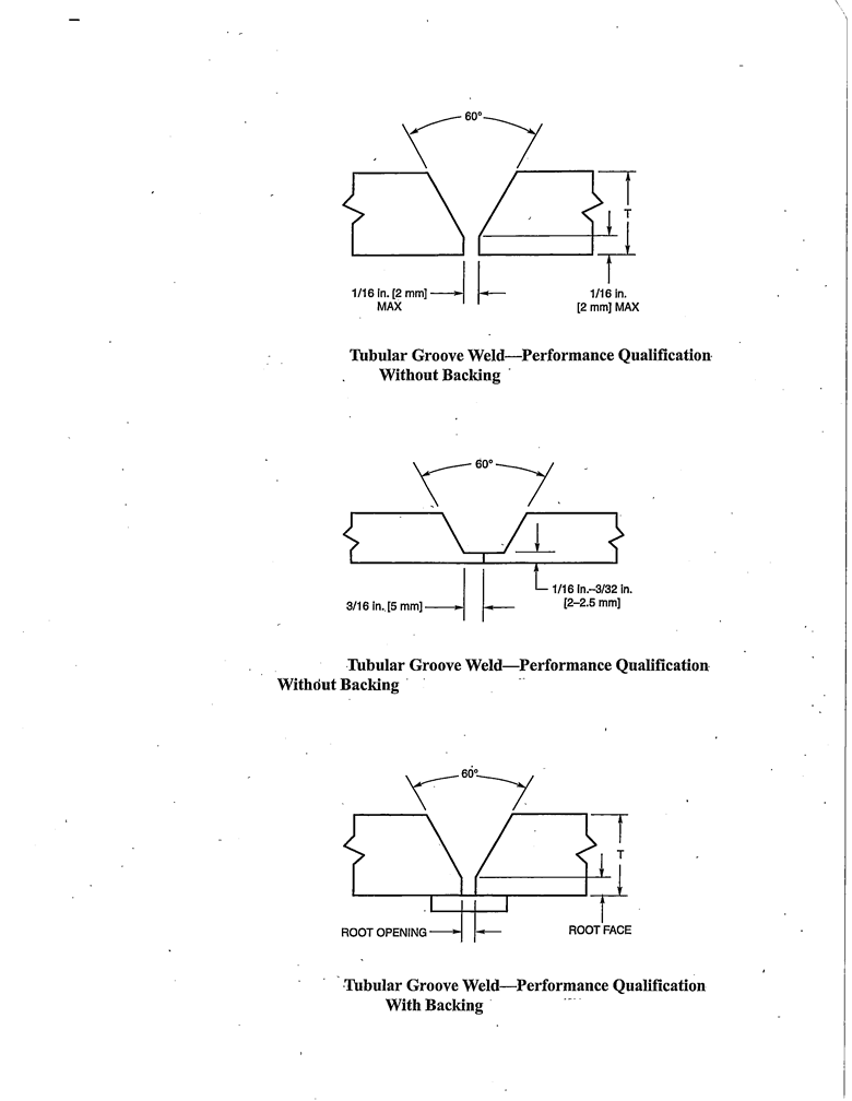
Pipe – Groove – 1G (Horizontal Rotated), 2G (Vertical Fixed), 5G (Horizontal Fixed), 6G (Inclined Fixed)
Pipe – Fillet – 1F (Inclined Rotated), 2F (Vertical Fixed), 2FR (Horizontal Rotated), 4F (Overhead Fixed), 5F (Horizontal Fixed)
WELDER PERFORMANCE
- All shop welders, welding operators and tack welders shall be qualified and certified prior to welding on any Iowa Department of Transportation Bridge or sign support structure. The qualification of welders, welding operators, and tackers shall be in accordance with the instructions of this IM. Certification shall be for a period of 1 year. However, shop welders certification may be extended annually based on a verification, notorized letter from the fabricator, certifying that the welder or tack welder has been engaged in the welding process for which he is qualified without interruption of more than six months during the preceding twelve months.
- All field welders shall be qualified for a period of one year. Those welders who have successfully passed their qualification tests without failure for two consecutive years, requalification will only be required every two years.
- Welder re-qualification/re-certification may be required at any time there is a specific reason to question his/her ability to make sound welds.
LIMITATION OF VARIBLE
- When welding in vertical position, a change in direction of welding shall require a re-qualification.
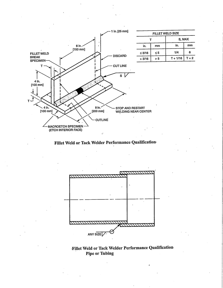
- Qualification of a tack welder. Tack welder shall be qualified as a welder of fillet welds in the qualified position.
FILLET WELD QUALIFICATION
Fillet welds between parts having dihedral angle of less than 75 degrees, the welder shall be required to weld a groove weld test plate. Parts having a dihedral angle of 75 degree to 135 degrees, shall be required to weld a fillet weld test plate.
Performance Accepting Criteria for Groove welds:
Visual examination shall be required for appearance and dimensions shall be in accordance with Part B, Section 3.6.3
The guided bend surface of the weld and the heat affected zone shall have no discontinuities exceeding the following dimensions:
a. 1/8” measured in any direction
b. 3/8” for the sum of all the discontinuities exceeding 1/32”, but less than or equal to 1/8” for 1 ½” wide specimens.
c. ¼” maximum for corner cracks, except when this crack has resulted from a visible inclusion or other fusion type of discontinuities, then 1/8” maximum shall apply.
Fillet Welds Fracture Test Requirements:
The 6 inch performance specimen, center section shall be examined visually on the broken surface. In order to pass, it must show complete fusion to the root and have no inclusion or porosity larger than 3/32” in the greatest dimension. The sum of greatest dimensions of all inclusions and porosity combined shall not exceed ¾” in the 6” length.
Note: The macroetch specimen for the fillet weld test (option #1) shall show complete penetration to the root of the joint.