GENERAL
Supports for reinforcing steel in Section 2404.03, E come in various sizes and types. These types have specific names such as slab bolsters, high chairs or continuous high chairs. The supports are used to hold reinforcing steel in place while concrete is being placed. They are typically made of small diameter steel rods, steel wire, or various shapes of molded plastic.
Contractors shall take care to utilize reinforcing steel supports with sufficient load ratings for their intended operations.
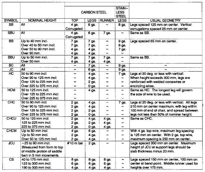
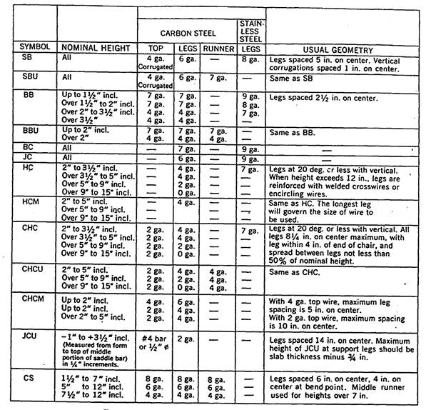
Table 1 identifies the various configurations of steel wire supports available. Table 2 lists the minimum sizes of steel wire required for the supports. Approval is based on meeting the minimum wire diameter sizes listed in Table 2.
Approved sources and brands of plastic supports can be found in the Materials Approved Products Listing Enterprise (MAPLE).
The signed mill test reports/certification for the steel supports shall include a statement indicating the steel meets the requirements of IM 107, Group 2, Buy America. Plastic supports must meet requirements of IM 107.
APPROVAL PROCESS
A manufacturer of plastic
supports, wishing to obtain approval shall submit the following to the Construction
and Materials Bureau in Ames, Iowa:
1. A request shall be submitted to the Construction and Materials Bureau in Ames, Iowa detailing the location of the manufacturing plant.
2. Technical Product Information and confirmation the support is made in America.
3. Samples:
For individual chairs - 5 pieces
For continuous support - 10 feet
4. Testing records shall be supplied as outlined in section 3.2.3 of ANSI / CRSI – RB4.1. Certification from an independent lab or facility that the Supports and/or Spacers meet these requirements may be substituted for the testing records. The certification for the product would contain: Load Category: No rating, 200, 400, 600 or 800 lb, Impact test: pass or fail, Water absorption criteria ( for polymers only ) : Pass or fail, Concrete Consolidation test: Pass or Fail.
Upon satisfactory review of this application, the source will be placed on the approved list in Appendix A.
TESTING PROCEDURE
See ANSI / CRSI – RB4.1 for testing requirements or they may be qualified as follows:
The testing procedure involves determining a point load limit for all supports and also a linear load limit for continuous devices.
The point load limit is determined by placing a #4 reinforcing bar on the support. The support is then placed on a 3/4 inch piece of fir plywood. A load is applied to the bar at a rate of 0.5 inch deflection per minute until the support fails. Point loads are determined at the weakest point on continuous supports.
The linear load limit is determined by placing a 1 foot plate on top of the continuous support. The support is again placed on a 3/4 inch piece of fir plywood and loaded at 0.5 inch deflection per minute until the support fails.
The supports fail in one of three principle ways:
1. Breaking
2. Excessive bending or deformation - more than 1/2 inch
3. Excessive gouging into the plywood - more than 0.1 inch
ACCEPTANCE
Steel supports will be accepted based on meeting the minimum wire diameter based on the type and size as listed in Table 1 and Table 2. There is not an approved suppliers list for steel supports.
Plastic supports will be accepted based on approved brands as noted in Appendix A and IM 107 certification of compliance.
TABLE 1 METRIC - TYPICAL TYPE & SIZES OF WIRE BAR SUPPORTS
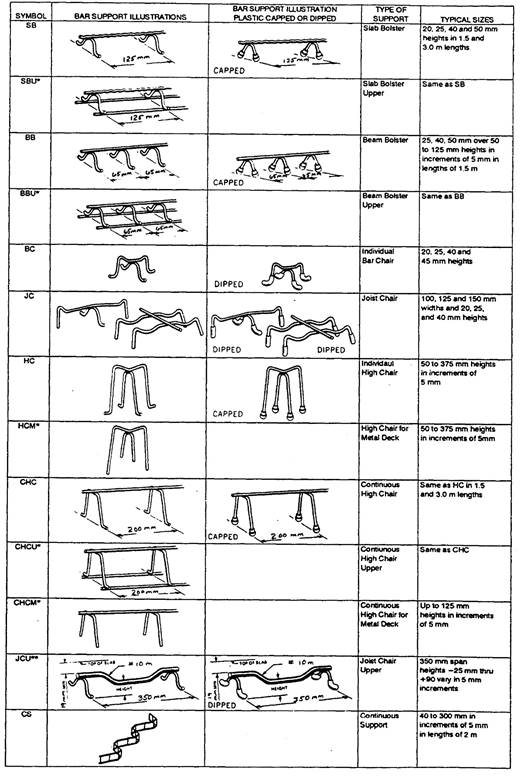
TABLE 2 METRIC – MINIMUM WIRE SIZES
|
Gauge |
Decimal Equivalent (mm) |
|
|
|
|
0 |
7.78 |
|
1 |
7.19 |
|
2 |
6.67 |
|
3 |
6.19 |
|
4 |
5.72 |
|
5 |
5.26 |
|
6 |
4.88 |
|
7 |
4.49 |
|
8 |
4.11 |
|
9 |
3.77 |
TABLE 1 ENGLISH – TYPICAL TYPE & SIZES OF WIRE BAR SUPPORTS
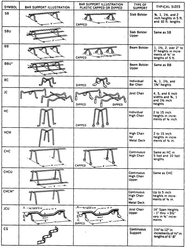
TABLE 2 ENGLISH - MINIMUM WIRE SIZES
|
Gauge |
Decimal Equivalent (Inches) |
|
|
|
|
0 |
.3065 |
|
1 |
.2830 |
|
2 |
.2625 |
|
3 |
.2437 |
|
4 |
.2253 |
|
5 |
.2070 |
|
6 |
.1920 |
|
7 |
.1770 |
|
8 |
.1620 |
|
9 |
.1483 |