SCOPE
This test method is intended to determine the specific gravity and absorption of combined aggregate for asphalt mix designs only. This method uses a flask pycnometer and a vacuum system.
REFERENCED DOCUMENTS
AASHTO T209 Theoretical Maximum Specific Gravity and Density of Bituminous Paving Mixtures
IM 336 Methods of Reducing Aggregate Field Samples to Test Samples
TEST METHOD
A. Apparatus
1. Balance, 10,000-gram minimum capacity and capable of weighing to the nearest 0.1 gram.
2. Pycnometer, four-liter, thick-walled, glass Erlenmeyer flask (without side discharge nozzle, with top surface of opening ground plane and smooth, and with rubber stopper hose connection) or other suitable pycnometer.
3. Vacuum pump or water aspirator for evacuating air from the pycnometer.
4. Thermometers, ASTM 15F (30°F to 180°F [ASTM 15C (2°C to 80°C)]), softening point and a general-purpose thermometer of suitable range with graduations every 0.5°F (0.2°C).
5. Large, flat weighing pan about 16 in. by 24 in. by 2 3/4 in. with one end formed in the shape of a chute, for cooling and weighing the sample and for transferring the sample into the pycnometer.
6. Glass 4 in. by 4 in. cover plate for accurate filling of pycnometer flask. This is for use with the glass flask.
7. Scoop, spatula or trowel, and bulb syringe.
8. Elevated water container, with gravity discharge valve and tubing, of sufficient capacity to conduct a complete test.
9. Funnel for transferring sample from weighing pan into the pycnometer.
|
NOTE: The manometer must not be connected to the vacuum tube coming from the pump, but is to be connected to the pycnometer through a separate tube. |
10. Manometer for measuring absolute pressure.
11. Equipment meeting AASHTO T-209 or ASTM D-2041 will also be considered acceptable.
B. Pycnometer Calibration
Prior to being put in service, a pycnometer calibration will be performed by accurately determining the mass of water at 77°F ± 0.5°F (25°C ± 0.2°C) required to fill the pycnometer. Accurate filling of the pycnometer is assured by the use of a cover plate.
|
NOTE: It is necessary to verify the calibration of each pycnometer before using and to periodically check the calibration thereafter to detect any change in weight due to wear or changes in the mineral content of the water. This is done by accurately filling the pycnometer with water at any temperature recorded on the calibration sheet, drying the outside of the pycnometer, and weighing the pycnometer, water, and proper cover plate. |
|
NOTE: Cover plate and pycnometer combinations are not interchangeable! The cover plate used for calibration should also be used for routine testing. If a different cover plate is used, however, the calibrated weight used in the specific gravity determinations must be appropriately adjusted by the difference in weight between the original cover plate and its replacement. |
This applies to both Erlenmeyer flask apparatus and the alternate equipment identified in A11 above.
C. Specific Gravity Test Procedure
1. Obtain a test sample of at least 2000 grams of oven dried individual source aggregate or combined aggregate. Combined aggregate samples are built up to asphalt mix design proportions by following IM 336.
2. Weigh the oven-dried test sample to the nearest 0.1 gram.
3. Transfer the sample into the calibrated pycnometer, which contains water to a depth of about 2 1/2 in.
4. Add water, if necessary to cover the sample. Agitate the sample to remove any loosely trapped air.
5. Insert rubber stopper and connect vacuum hose. Apply a vacuum to attain between 1.0 in. and 1.2 in. (25.5 mm and 30 mm) Hg (mercury) absolute pressure, as measured by a manometer, to the flask contents for 30 minutes. During the vacuum time period agitate the flask and contents continually by using a mechanical vibratory device, or manually by shaking and rolling the flask at intervals of about 2 minutes. This will facilitate the removal of air bubbles trapped in the sample and on the interior surface of the glass.
6. Remove the vacuum apparatus from the pycnometer and fill with water to the top of the neck of the pycnometer. Allow the water filled pycnometer to stand for 20 minutes.
7. Tip the pycnometer slightly and use a glass cover plate and bulb syringe to add water until the pycnometer is completely full.
8. Dry the outside of the pycnometer and glass plate with a clean cloth, chamois or paper towel, and weigh to the nearest 0.1 gram. Immediately after weighing, remove the glass plate and determine the temperature of the water to the nearest 0.5°F (0.2°C) degree with the general-purpose thermometer.
D. Calculation of Vacuum Apparent Specific Gravity (Gsa)
Calculate the vacuum apparent specific gravity (lines 1 through 11 of the data sheet, Appendix A) of the aggregate sample as follows:
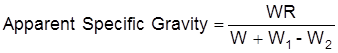
Where: W = weight of dry sample, grams
W1 = weight of pycnometer filled with water at test temperature, grams. (This value must be determined anytime the test temperature changes from the calibration temperature by more than ± 0.5°F (± 0.3°C)
W2 = weight of pycnometer filled with water and sample, grams
R = correction multiplier (from table)
![]()
Where: dt = density of water at test temperature, grams/cc (from table)
0.99707 = density of water at 77°F (25°C) grams/cc
E. Absorption Test Procedure
1. After determining the specific gravity, pour water from the sample through a No. 200 (75-μm) mesh sieve.
2. Remove the sample from the flask and wash the sample over a No. 200 (75-μm) mesh sieve.
3. Split the sample on a No. 8 (2.36-mm) sieve. This may require using water. If water is used, the wash water from the fine portion is passed through a No. 200 (75-μm) sieve.
|
NOTE: If less than 10% of the material passes the No. 8 (2.36-mm) sieve, the material passing the No. 8 (2.36-mm) sieve may be discarded.
NOTE: If more than 90% of the material passes the No. 8 (2.36-mm) sieve, the material retained on the No. 8 (2.36-mm) sieve may be discarded. |
4. Place the coarse portion [plus No. 8 (2.36-mm) sieve] of the sample on a bath towel and roll the sample around by holding on to each end of the towel. (The towel will absorb most of the free water from the aggregate particles.)
5. Place the coarse portion of the sample in a large, flat pan or on a clean hard surface. Observe when the particles develop a dull appearance and leave no streaks of moisture when moved indicating a saturated surface-dry (SSD) condition. This usually requires only about 2 to 3 minutes.
6. After the coarse particles obtain an SSD appearance immediately weigh to the nearest 0.1 gram.
7. Place the fine portion [minus No. 8 (2.36-mm) sieve] in a large pan and dry to a SSD condition by stirring and turning the particles continuously so they will dry evenly. When the material becomes free flowing and there is no tendency for the finer particles to adhere to a cool, dry steel spatula, the material is considered to be in a SSD condition.
To aid the removal of the free water, the fine sample may be placed in a 150-mm or larger Buchner funnel containing an appropriate filter paper. A vacuum is then applied to the flask, which collects the water until the water is dripping from the funnel at a rate of 1 to 2 drops per second. The fine sample is then transferred to the large, flat pan for drying to a SSD condition as above.
The use of a hot plate placed in front of, or in back of, a fan to circulate air over the sample to aid in obtaining an SSD condition is permissible.
|
NOTE: Free water accumulates at the bottom of the pan. Paper towel may be used to dry the pan. DO NOT attempt to dry the sample with the paper towel. |
8. Immediately after the fine portion of the sample has attained an SSD condition, weigh to the nearest 0.1-gram.
9. Re-combine the coarse and fine portions of the saturated-surface-dry sample, dry to a constant weight (mass) on a hot plate or in an oven and weigh to the nearest 0.1-gram (coarse and fine portions may be dried separately).
F. Calculation of Water Absorption, %Abs (Vacuum Method)
Calculate the water absorption (lines 12 through 17 of the data sheet, Appendix A) of the aggregate sample as follows:

Where: Wa = saturated surface-dry (SSD) weight of coarse portion
Wb = saturated surface-dry (SSD) weight of fine portion
Wc = combined dry weight of coarse and fine portion
G. Bulk Dry Specific Gravity (Gsb)
This test method determines the vacuum apparent specific gravity (Gsa) of individual or combined aggregate sources. For the purpose of asphalt mix design; the aggregate bulk specific gravity (Gsb) is needed. Aggregate bulk specific gravity (lines 18 through 20 of the data sheet, Appendix A) may be determined from apparent specific gravities as follows:
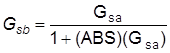
Where: ABS = %Abs/100
%Abs = percent absorption
|
CORRECTION MULTIPLIER FOR SPECIFIC GRAVITY DETERMINATION |
||||||||||
|
|
||||||||||
|
TABLE 1 – DENSITY OF WATER (°C) |
||||||||||
|
|
||||||||||
|
°C |
0 |
1 |
2 |
3 |
4 |
5 |
6 |
7 |
8 |
9 |
|
10 |
0.99973 |
0.999633 |
0.999525 |
0.999404 |
0.999271 |
0.999127 |
0.998971 |
0.998803 |
0.998624 |
0.998435 |
|
20 |
0.99823 |
0.998023 |
0.997802 |
0.997570 |
0.997329 |
0.997077 |
0.996816 |
0.996545 |
0.996265 |
0.995976 |
|
30 |
0.99568 |
0.995371 |
0.995056 |
0.994733 |
0.994400 |
0.994061 |
0.993714 |
0.993359 |
0.992996 |
0.992626 |
|
40 |
0.99225 |
0.99187 |
0.99147 |
0.99107 |
0.99066 |
0.99025 |
0.98982 |
0.98940 |
0.98896 |
0.98852 |
|
50 |
0.98807 |
0.98762 |
0.98715 |
0.98669 |
0.98621 |
0.98573 |
|
|
|
|
|
|
||||||||||
|
|
||||||||||
|
TABLE 2 – R CORRECTION MULTIPLIER (Correction to 25°C) |
||||||||||
|
|
||||||||||
|
°C |
0 |
1 |
2 |
3 |
4 |
5 |
6 |
7 |
8 |
9 |
|
10 |
1.0027 |
1.0026 |
1.0025 |
1.0023 |
1.0022 |
1.0021 |
1.0019 |
1.0017 |
1.0016 |
1.0014 |
|
20 |
1.0012 |
1.0009 |
1.0007 |
1.0005 |
1.0003 |
1.0000 |
0.9997 |
0.9995 |
0.9992 |
0.9989 |
|
30 |
0.9986 |
0.9983 |
0.9980 |
0.9976 |
0.9973 |
0.9970 |
0.9966 |
0.9963 |
0.9959 |
0.9955 |
|
40 |
0.9952 |
0.9948 |
0.9944 |
0.9940 |
0.9936 |
0.9932 |
0.9927 |
0.9923 |
0.9919 |
0.9914 |
|
50 |
0.9910 |
0.9905 |
0.9900 |
0.9896 |
0.9891 |
0.9886 |
|
|
|
|
|
|
||||||||||
|
|
||||||||||
|
TABLE 3 – DENSITY OF WATER (°F) |
||||||||||
|
|
||||||||||
|
°F |
0 |
1 |
2 |
3 |
4 |
5 |
6 |
7 |
8 |
9 |
|
60 |
0.999040 |
0.998982 |
0.998859 |
0.998764 |
0.998664 |
0.998562 |
0.998455 |
0.998346 |
0.998232 |
0.998115 |
|
70 |
0.997997 |
0.997874 |
0.997749 |
0.997619 |
0.997489 |
0.997353 |
0.997216 |
0.997074 |
0.996929 |
0.996783 |
|
80 |
0.996632 |
0.996481 |
0.996325 |
0.996168 |
0.996006 |
0.995844 |
0.995676 |
0.995505 |
0.995335 |
0.995159 |
|
90 |
0.994984 |
0.994802 |
0.994622 |
0.994436 |
0.994251 |
0.994059 |
0.993866 |
0.993673 |
0.993475 |
0.993277 |
|
100 |
0.993074 |
0.992872 |
0.992664 |
0.992458 |
0.992246 |
0.992030 |
0.99182 |
0.99160 |
0.99138 |
0.99116 |
|
110 |
0.99093 |
0.99071 |
0.99048 |
0.99025 |
0.99001 |
0.98977 |
0.98954 |
0.98930 |
0.98906 |
0.98881 |
|
120 |
0.98857 |
0.98832 |
0.98807 |
0.98782 |
0.98757 |
0.98731 |
0.98705 |
0.98679 |
0.98653 |
0.98626 |
|
130 |
0.98606 |
|
|
|
|
|
|
|
|
|
|
|
||||||||||
|
|
||||||||||
|
TABLE 4 – R CORRECTION MULTIPLIER (Correction to 77°F) |
||||||||||
|
|
||||||||||
|
°F |
0 |
1 |
2 |
3 |
4 |
5 |
6 |
7 |
8 |
9 |
|
60 |
1.0020 |
1.0019 |
1.0018 |
1.0017 |
1.0016 |
1.0015 |
1.0014 |
1.0013 |
1.0012 |
1.0010 |
|
70 |
1.0009 |
1.0008 |
1.0007 |
1.0005 |
1.0004 |
1.0003 |
1.0001 |
1.0000 |
0.9999 |
0.9997 |
|
80 |
0.9996 |
0.9994 |
0.9992 |
0.9991 |
0.9989 |
0.9988 |
0.9986 |
0.9984 |
0.9983 |
0.9981 |
|
90 |
0.9979 |
0.9977 |
0.9975 |
0.9974 |
0.9972 |
0.9970 |
0.9968 |
0.9966 |
0.9964 |
0.9962 |
|
100 |
0.9960 |
0.9958 |
0.9956 |
0.9954 |
0.9952 |
0.9949 |
0.9947 |
0.9945 |
0.9943 |
0.9941 |
|
110 |
0.9938 |
0.9936 |
0.9934 |
0.9932 |
0.9929 |
0.9927 |
0.9924 |
0.9922 |
0.9920 |
0.9917 |
|
120 |
0.9915 |
0.9912 |
0.9910 |
0.9907 |
0.9905 |
0.9902 |
0.9899 |
0.9897 |
0.9894 |
0.9892 |
|
130 |
0.9890 |
|
|
|
|
|
|
|
|
|