SCOPE
The proper amount of PC Concrete cover over reinforcing steel is very important to the service life of bridge decks. Adequate cover is needed to protect the steel from the corrosive effect of the de-icing salts used in winter maintenance. Thin cover allows the de-icing salts to cause rusting of the steel. As steel rusts, it expands which builds up a force that results in spalling or loosening of the concrete above the reinforcing steel.
PURPOSE
The purpose of this test is to measure the amount of concrete cover over the reinforcing steel to determine:
1. If bridge decks have adequate cover.
2. The areas on bridge decks exhibiting insufficient cover.
PROCEDURE
A. Determine layout of a systematic pattern for making spot-checks of the steel cover.
1. Obtain a set of plans for the bridge deck to be checked.
2. Use the left curb line as a reference for lateral measurements.
3. Layout Method A: Lay out the points for spot checks on lateral location lines spaced at 8 ft. intervals (measured perpendicular from the curb), except the first longitudinal line will be 1 foot from the left curb face and the last will be 1 foot from the right curb 1ft., 9 ft., 17 ft., 25 ft., etc., deck width minus 1 ft.
Layout Method B: Lay out the points for spot checks on lateral location lines spaced at 8 ft. intervals (measured on a line parallel with the centerline of abutment bearing or pier), except that the first longitudinal line will be 1 ft. from the left curb face (on the skew) and the last will be 1 ft. from the right curb (as in Method A, except measured on the skew).
4. Spot checks will be made on the intersection of the longitudinal line with transverse lines spaced at 10 ft. intervals from the beginning (lowest station) point of each span.
B. Apparatus
1. A model C-4921 James Electronics pachometer (Figure 1)
2. One calibration box (Figure 1) with a No. 6 bar
a. A full set will be available at the Central Laboratory for complete calibration.
- A metric (100 ft.) measuring tape
C. Graphs and Record Forms
1. A calibration graph with curves for various reinforcing bar sizes (Figure 2)
2. Form No. #1239, Cover of Steel on Bridge Decks (Figure 3)
D. Test Procedure
1. Calibration
a. Turn on the pachometer and allow a 20-minute warm up before use.
b. Using the following procedure, obtain a calibration curve.
2. Adjust the pachometer to read exactly 100 with the probe plugged in beyond any influence of magnetic materials.
3. With the probe ends in contact with the surface of the calibration box and the longitudinal axis of the probe in the same direction as that of the rebar, move the probe side-to-side over the rebar. Determine the lowest meter reading obtained and record it. If there are two low-reading points and a higher reading immediately over the rebar, the cover is too thin to yield a valid reading.
4. Using this procedure, determine the minimum readings for a 2 3/4 in. and each 1/4 in. increment of decrease down to 1 in. or the least cover that will yield a valid reading. Repeat this procedure three times while checking frequently to verify that the meter reads 100 when beyond the influence of steel. Average the three readings to determine the value to be used in plotting the calibration graph. Plot the graph on ten-division graph paper.
5. Determine the calibration curves for Nos. 5, 6, 7, 8 and 9 rebars.
6. Field Test
a. Using the plans, determine the skew (if any) to assist in laying out the locations for spot check as described in Step A above.
b. Mark the points for spot checks with keel.
c. Allow the pachometer to warm up for 20 minutes before testing begins.
d. From the plans, determine the size, direction and design cover of the top steel. Record the size and design cover on Form #1239.
e. Check the pachometer on the calibration box before making any cover thickness determinations to verify correctness. Repeat this procedure before each half-day's testing.
f. With the probe ends in contact with the bridge deck surface, turn the longitudinal axis of the probe in the general direction of the top rebar. Move the probe from side-to-side and locate the position giving the lowest meter reading. After locating the proper position, rotate the probe slightly each way to see if a better alignment will yield a lower meter reading. Record the lowest meter reading that can be obtained to the closest whole number.
g. Using this meter reading and the calibration curve for the proper bar size, determine the thickness of cover to the closest 0.4 in.
h. If the cover is too thin to yield a valid reading, use a sufficient thickness of nonmagnetic shims and determine a valid reading using the shims. Determine the cover as in point g and subtract the shim thickness to obtain the steel cover.
i. In this manner determine the steel cover at all predetermined spot check locations.
E. Reporting
1. Record data on Form #1239, Cover of Steel on Bridge Decks.
a. The distribution shall be noted in the upper right-hand corner.
b. From the plans and project file, record all the data requested in the heading section.
c. Field Data
(1) After laying out points for the spot checks, record the distances from the left curb of the lateral location lines across the top of the table.
(2) Record the number of 10-ft. longitudinal intervals within each span down the left-hand column.
(3) There is a three-part space provided for each spot check point. In the upper left space, record the meter reading to the nearest whole number. If a shim is used, put the shim thickness in the lower left corner. Using this data and the calibration curve, record the thickness of cover in the right-hand space.
d. After obtaining all field data, calculate the total number of readings, the average cover, and the percent of readings less than the design cover and record them at the bottom of the sheet.
e. The engineer in charge of the test personnel should sign this form.
F. Precautions
1. Be positive that the batteries are well charged for proper operation and assure the batteries will not rupture causing the meter to be inoperable due to internal corrosion. If the meter is not to be used for a long period of time, remove the batteries.
2. Avoid any jarring or shocking of the meter to prevent malfunctions.
3. Check often to assure that the meter reads 100 when beyond the influence of any magnetic materials.
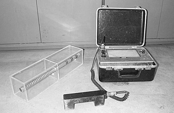
Figure 1
Figure 2
![]()