This method covers the procedure for determining the length of a core drilled from a PC Concrete structure, particularly from a PC Concrete pavement. The procedure is a modification of AASHTO T 148.
PROCEDURE
A. Apparatus
1. The apparatus consists of a calipering device that will measure the length of axial elements of the core.
2. The apparatus is designed so the specimen is held with its axis in a horizontal position by guide rods when making circumferential measurements, and a stand placed upon the guide rods for making a center measurement. The device is equipped with an auxiliary wheel that rests on the specimen and is calibrated such that one-half of a revolution of the wheel represents one-eighth the circumference of a 4 in. (100 mm) diameter core.
3. The device is constructed so the specimen is brought into contact with a single flat-faced probe 3/8 in. (10 mm) in diameter mounted on a fixed end of the device.
4. The measuring rod, which makes contact with the end surface of the specimen, is rounded to a radius of 1/8 in. (3 mm) and is mounted on a moveable plate, which in turn is mounted on guide rods. One guide rod is provided with a scale on which the length readings are made. The graduations of the scale are spaced at 0.10 in. (2.5 mm) intervals.
5. The apparatus provides for the accommodation of specimens of different nominal lengths over a range of 4 to 11 in. (100 mm to 275 mm).
6. The calipering apparatus is designed so it is possible to make a length measurement at the center of the specimen and at eight additional points spaced equally along the circumference of a circle whose center point coincides with the end area of the specimen and whose radius is not less than one-half, nor more than three-fourths, of the radius of the specimen.
7. The apparatus is stable and sufficiently rigid to maintain its shape and alignment without a distortion or deflection of more than 0.01 in. (0.25 mm) during all normal measuring operations.
B. Test Specimens
1. Cores used as specimens for length measurement must be in every way representative of the concrete in the structure from which they are removed. The specimen is to be drilled with the axis normal to the surface of the structure, and the ends must be free from all conditions not typical of the surfaces of the structure. A large screwdriver, hammer and wire brush may be used to force subbase material from the bottom of the core. Use enough force to remove the material, but not cause damage to the core. If the material is firmly cemented, or encased in mortar, it may not be possible to remove. (Figures 2 and 3) Cores that show abnormal defects or that have been damaged appreciably in the drilling operation should not be used.
C. Test Procedure
1. Before any measurements of the core length are made, calibrate the apparatus with suitable gauges so errors caused by mechanical imperfections are known. When these errors exceed 0.01 in. (0.25 mm), suitable corrections must be applied to the core length measurements.
2. Place the stand on the guide rods and place the specimen on the stand for the center point measurement. The smooth end of the core, that is, the end that represents the upper surface of a pavement slab or a formed surface in the case of other structures is to be positioned facing the fixed end of the measuring device. Bring the specimen into contact with the stud in the fixed end, slide the movable plate until it is in contact with the specimen and record the length.
3. Remove the stand, place the specimen directly on the guide rods and make another measurement as described in C2.
4. Place the small auxiliary wheel on the specimen so the scribed marks on the wheel are in alignment. Rotate the specimen until the marks are again in alignment (1/2 revolution of the wheel) and make another measurement. Continue in this manner until eight measurements in addition to the center measurements have been made. If the core is not 4 inches in diameter (typically 3.75 or 4.25 inches), the DME may allow alternative methods to be used.
5. Read each of the nine measurements directly to 0.10 in. (2.5 mm), and interpolate to the nearest 0.05 in. (1 mm) by estimation.
6. If, in the course of the measuring operation, it is discovered that at one or more of the eight circumferential measuring points the surface of the specimen is not representative of the general plane of the core end because of a small projection or depression, rotate the specimen slightly about its axis, and make another set of measurements with the specimen in the new position. If the center measurement is not representative of the general plane of the core end, it should not be used in computing the length of the core.
7. If some damage from drilling is apparent, no measurements are to be made in the damaged area. Reposition the core to avoid the areas when measuring the length. If these areas cannot be avoided, the length measurements made in these areas are not to be used in computing the length of the core. In no case, are fewer than seven measurements to be used in determining the core length.
D. Report
1. The individual observations are to be recorded to the nearest 0.05 in. (1 mm) and the average of the nine measurements expressed to the nearest 0.05 in. (1 mm) and shall be reported as the length of the concrete core.
E. Precautions
1. Be careful to move the core away from the stud in the fixed end slightly when turned, so the stud will retain its proper length and shape.
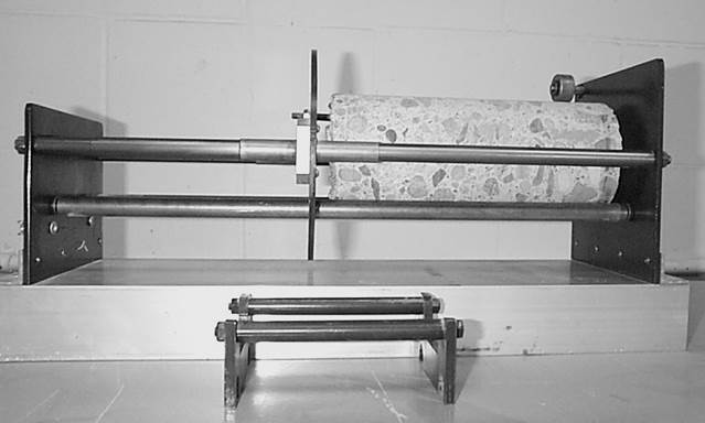
Figure 1. Concrete Core in Measuring Apparatus
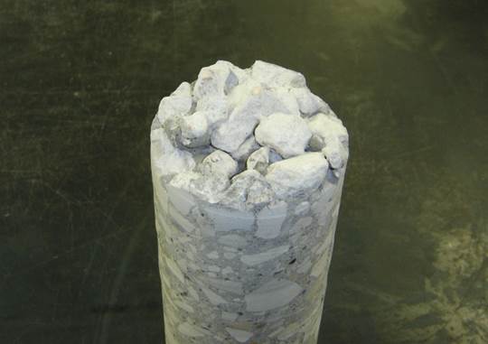
Figure 2. Concrete core with granular subbase attached.
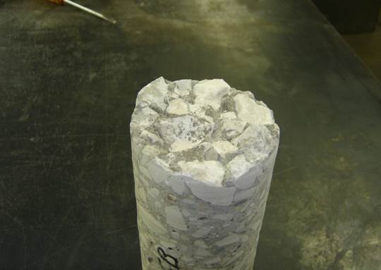
Figure 3. Concrete core with granular subbase removed.