SCOPE
Portland Cement Concrete (PCC) pavement will be evaluated to determine the pavement thickness, in accordance with Article 2301.04. The thickness index will be determined for each section, in accordance with Article 2301.05.
The District Materials Engineer will determine identification of the limits of each lot and the random test locations. The engineer will determine the average thickness and calculate the thickness index to determine payment to the Contractor from the payment schedule.
Thickness evaluation may be performed by Method A non-destructive measurement using a MIT Scan T2 or T3 device or by Method B drilling cores.
DEFINITIONS
Section: All Portland Cement Concrete in a project of the same bid item. Irregular areas, as defined herein, of the same bid item shall form a separate section. On multiple year projects, a separate section will be formed for each year. If less than 20,000 square yards are placed in one year, that section will be grouped with a previous or subsequent year.
Regular area pavement sections are defined as follows:
· All mainline pavement for normal travel lanes.
· Paved shoulder – if same thickness as pavement and part of pavement bid item include with pavement. If separate bid item, treat as separate section.
· Paved median - if same thickness as pavement and part of pavement bid item, and longer than 300 feet, include with pavement.
· Widening greater than six feet and longer than 300 feet.
· Auxiliary lanes, ramps, deceleration and acceleration lanes, collector distributor roads, and side street connections of full width and longer than 300 feet.
Irregular areas are defined as follows:
· Widening, six feet or less.
· Ramp taper and gore areas.
· Turn lanes, including taper sections.
· Tapers.
· Radiuses.
· Median crossovers.
Lot: A portion of a section. Each lot is represented by a randomly located thickness measurement as part of the dataset that will represent the section.
Segments: A portion of a lot.
See Figure 1 in Appendix A for an illustration
of the elements described above. See Article 2301.0 4 of the Standard
Specifications regarding sections of 3500 sq. yd or less.
Method A – Non-Destructive Thickness
Equipment
A. An MIT Scan T2 or T3 gauge will be used to perform thickness measures.
B. Steel targets will be 11.81 inches in diameter, 24 gauge, meeting ASTM A 653, commercial steel with a G90 coating (about 275 g/m2 total both sides).
Procedure
The District Materials Engineer will determine the location of each lot, the random location of each metal target, and the random thickness measuring scheme for each section using the Iowa DOT MIT Location MSExcel spreadsheet.
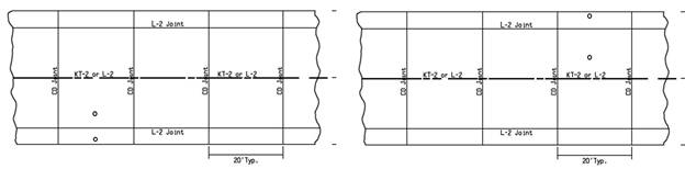
A. Target Location for Regular Areas
- Lots-Mainline.
Divide the section longitudinally into 200 foot long lots. One target will
be located in each lot based on the spreadsheet selection. Beginning with
the first station at +00, place a target from the edge of the pavement
half way between dowel baskets
). See Figure 1. If the +00 station falls on a basket, move the target location ahead halfway between the dowel baskets. A minimum of ten targets will be tested. If a target location falls on a bridge or in an approach section, it will be eliminated.
- Segment. The transverse location of the targets will be randomly determined by the spreadsheet program. The random locations will be either 4 or 8 feet from edge of pavement, left or right.
- Target Location. The program will randomly determine which targets to measure. Press F9 in the spreadsheet to randomly select approximately 50-60 percent tested for mainline and approximately 30-40% for shouders. If a measurement location falls on a bridge or bridge approach pavement, it will be eliminated and the next closest target not in the original random selection will be used for measurement.
- Shoulders. Divide the section into 200 foot long lots. Beginning with the first station at +00, locate a target every 200 feet, alternating between the inside and outside shoulder (or every 400 feet on one side). On 6 foot shoulders or wider, the targets should be 4 feet from the edge of the pavement. On 4 foot shoulders, the targets should be 3 feet from the edge of the pavement.Press F9 in the spreadsheet to randomly select 30 to 40 percent tested.
Figure1. Target Location
B. Target Location for Irregular Areas
1. All irregular areas of the same design thickness will be grouped together for determining the number of lots. The Engineer may waive sections of the same design thickness that total less than 3500 square yards.
2. Place targets randomly in all irregular areas larger than 100 square yards. One target will be randomly located in each selected irregular area. For irregular areas greater than 1000 square yards, randomly place a minimum of two targets. Targets must be placed at least 2 feet away from tie steel and 4 feet from dowel bars. A minimum of ten targets will be tested to represent each section of irregular areas. For projects with less than ten irregular areas larger than 100 square yards, select a minimum of three areas to place targets. All targets will be measured. If more than 20 targets are located in irregular areas, randomly select 50% to be tested.
C. Testing
Follow the manufacturer’s instructions for operating the thickness gauge. It is important to avoid testing close to any steel including vehicles, equipment, steel toed shoes as well as tie bars, dowel bars and baskets, and manhole covers. When wearing steel toed shoes, always keep both toes at least 2 feet from the gauge during the test. Three repeat readings will be taken. The readings should all be within 3 mm (T2) or 0.15 inches (T3) of each other. If the difference between any of the readings is more than 3 mm (0.15 in.), take 2 additional readings. If the two additional readings are within 3 mm (0.15 in.) of any of the first 3 readings, the measurement is valid for that location. If not, note that the location is not valid and select the next target location not originally selected for testing.
Method B – Coring
Equipment
- Core drill rig
- A core drill bit with a 4 1/4 in. outside diameter usually has an inside diameter of 4 in.
Procedure
The District Materials Engineer will determine the location of each lot and the random location of each core, for each section using an Iowa DOT developed MSExcel spreadsheet
A. Core Location – Regular Areas
1. Lots-Mainline. Divide the section longitudinally into 2000 sq. yd. lots. If the last lot of the pavement section is less than 1000 sq. yd. group this lot with the last full 2000 sq. yd. lot, otherwise treat lots greater than 1000 sq. yd. as a lot by themselves. A minimum of ten cores is required. Sections less than 20,000 sq. yd. will be divided longitudinally into ten lots approximately equal in size. The width of the section shall be the pavement design width, regardless of placement width.
2. Segments. Divide the lots into six approximately equal segments, both longitudinally and transversely. Assign a number one through six to each longitudinal and each transverse segment.
3. Core Location. Select the segment to be cored within each lot separately, by rolling the die or other random selection method. Locate the core at the approximate midpoint transversely and longitudinally of the selected segment. No core shall be taken within 18 in. of a transverse joint. If any of the random core locations are placed in an area that is unable to be cored, such as a bridge deck, approach, etc., relocate the core one full station forward or backwards from the original random location.
4. Shoulders. Divide the section into 2000 sq. yd. lots. Divide each lot into six segments. Core a random segment at approximately mid point longitudinally and transversely.
Figure 2. Coring Location Layout
B. Irregular Areas
1. Sections. All irregular areas of the same design thickness shall be grouped together for determining number of lots.
2. Core Location. Irregular areas to be cored will be determined by random selection of all irregular areas larger than 100 sq. yd. One core will be randomly located in each selected irregular area. For projects with greater than ten irregular areas, a minimum of ten cores is required to represent each section of irregular areas. For projects with less than ten irregular areas larger than 100 sq. yd., select a minimum of three areas to be cored.
C. Testing. Measure length of drilled cores in accordance with IM 347.
D. Records
The Project Engineer will determine and record the locations daily. This information will be furnished to the Contractor daily for use in locating and cutting cores. The Project Engineer will witness the cutting of the cores.
E. Core Numbers
The engineer will assign all cores a number. The core numbers shall consist of the District number and a consecutive number beginning with 0001 and terminating at 9999.(For example, 10385 would be the 385th core recorded District 1 Materials Office.)
In the Remarks section, as shown in Appendix B of this IM, mark cores as D for deficient or R if a replacement core has been added.
Thickness Evaluation
A. Section Evaluation
1. Use the following formula to determine the mean thickness for the section:
![]()
![]()
![]()
![]()
![]()
Round the mean thickness to two decimal places.
2. Use the following formula to determine the sample standard deviation of the thickness of the section:
Where: ![]()
S = thickness standard deviation for the section.
![]() = mean thickness for
the section
= mean thickness for
the section
X = individual thickness values for the section.
n = number of tests representing the section.
Round the sample standard deviation to two decimal places.
NOTE: Use the Iowa DOT MSExcel spreadsheet for cores and the MIT gages to calculate the thickness index.
3. Use the following formula to determine the thickness index for the section of pavement thickness.
Where:
TI = thickness index for the section
![]() = mean thickness for
the section
= mean thickness for
the section
T = design thickness
S = thickness standard deviation (of the sample) for the section
Round the thickness index to two decimal places.
NOTE: If the mean thickness minus the standard deviation is less than the design thickness of the section, the thickness index will be a negative number.
4. Basis of Payment. Payment for the quantities of pavement in square yards in each section will be as shown in Article 2301.05 and based on the thickness index as determined in accordance with these instructions.
B. Deficient Areas
When using non-destructive evaluation, if any measurement is deficient from T by 1 inch or more, the measurement should be rechecked to confirm the reading and the equipment. If the repeat measurement is also 1 inch or more below T, mark the location directly over the target. The Contractor shall drill a 4.0 inch diameter core at that location. If the core length confirms the pavement is deficient by 1 inch or more, continue to drill cores as described below.
1. Deficient areas, represented by cores, or thickness measurement, deficient in length by 1 in. or more from design thickness, are to be replaced. These areas will be determined by drilling a core 60 ft. in each direction longitudinally at the same transverse location from the deficient core. Drilling will be continued at 60 ft. intervals until a core is obtained which is not deficient by 1 in. or more from design thickness. Interpolate between this core and the adjacent core to determine the limits of the deficient area. This is the area to be removed and replaced at contractor’s expense. These additional cores are to be used to define the deficient area and will not be used in the thickness index calculation. When an obstruction, such as a bridge, intersection, previous work, etc., prevents drilling a core at the required 60 ft. interval in either direction longitudinally, continue the balance of the distance on the other side of the obstruction.
5. To replace the original core taken from the deficient area, randomly select a core location in the remaining area of the original lot. This core length will be used for calculating the thickness index. If the remainder of the original lot is less than 1000 sq. yd., include this remaining area with the next full lot.
Reporting
A. Core Report
The engineer will report the results of the core measurements in the following manner:
1. The project information
will be reported on Form #130.
2. The distance from centerline and roadway width should be measured to the nearest 0.1 in.
3. The nine-point measurements should be reported on Form #130.
4. The contractor shall deliver the cores to the designated laboratory. Report #130 will accompany the cores when delivered to the contracting authority laboratory or office.
B. Non-Destructive Thickness Report
The District Materials Engineer will download the data from the MIT SCAN T2 or T3 gage and import the thickness measurements into Form #130MIT.
1. Assurance tests may be reported on the same form along with gage numbers and testing personnel
2. Report subbase type on the form to determine correction. The subbase correction may be found in the following table.
|
Type of Base, Subbase, Subgrade just below the concrete |
Value of T in Inches |
|
Natural Subgrade or Soil Aggregate Subbase |
Design Thickness |
|
HMA Base, PCC Base, or Asphalt or Cement Treated Base |
Design Thickness |
|
Modified Subbase or Special Subbase |
Design Thickness - 0.25 inches |
|
Granular Subbase |
Design Thickness - 0.35 inches |