SCOPE
This test method describes the field test procedure for determining the thickness of a non-magnetic coating on a magnetic substrate by use of a magnetic thickness gauge. This test method is the field procedure for Laboratory Test Method 803.
APPARATUS
1. Inspector gauge with 0-25 mil range or Mikrotest gauge with 0-40 mil range.
2. Calibration standards consisting of coatings of known thickness bonded to the substrate or plastic shims of known thickness and specimen of uncoated base metal (See section on standards).
INSTRUMENT OPERATION
1. Check the magnet tip to make sure it is clean.
2. Place the rubber housing of the magnet on the surface to be measured with the rear contact point of gauge on the same surface or other surface in the same plane. Position the gauge so the magnet is perpendicular to the surface at the contact point. (See Notes 1 and 2.)
3. Stabilize the gauge in the above position with your finger and/or thumb placed on the housing near the magnet (See Figure 1). Hold the gauge steady with firm but gentle downward pressure while operating (See Note 3).
4. Touch the magnet to the specimen surface.
5. Slowly rotate the dial clockwise until the magnet breaks contact. Separation can be heard or it can be seen by watching the colored pipe at front of the gauge (See Note 3).
6. Obtain the thickness measurement from the dial using the same reading mark as used for calibration. This will be either a stationary mark or a movable compensator.
CALIBRATION STANDARDS
The calibration standard used should be selected after consideration of the following factors:
1. Film Composition. The standard film composition should be about the same as the coating being tested, i.e., zinc films for galvanizing and paint films for painting. Plastic shims should only be used for curved surfaces coated with a paint-type material (not galvanizing).
2. Film Thickness. The standard film thickness should be as close as possible to thickness being measured. The approximate recommended thicknesses are:
|
Range of Sample |
Approximate Standard |
|
Thickness in mils |
Thickness in mils |
|
0.3 - 1.5 |
1 |
|
1.5 - 3.5 |
2 |
|
2.5 - 5.5 |
4 |
|
4 - 8 |
6 |
|
8 - 12 |
10 |
3. Substrate. The substrate of the standards should have the same magnetic properties, surface texture (sandblasted, smooth, etc.), curvature, and effective thickness as material being tested (See notes 4 and 5.).
INSTRUMENT CALIBRATION
1. Select a standard film of proper composition, thickness, and substrate.
2. Determine the average of five readings taken at different points on the standard film, using the stationary reading mark on the gauge.
3. On gauges with a compensator, rotate the dial so the stationary mark indicates measured thickness found in Step 2. Without moving the dial, set the compensator to indicate actual film thickness of the standard. Subsequent test measurements are read using the compensating mark (See Note 6).
4. If the gauge does not have a compensating mark, determine the difference between the actual standard film thickness and the average measured film thickness found in Step 2. Use this difference to correct subsequent test results (See Note 6).
TEST PROCEDURE
1. Calibrate the gauge as outlined above (See Note 7).
2. Select a small area [about 4 in. diameter or less] on a smooth portion of test surface. Remove all foreign material. Avoid areas difficult to clean.
3. Make at least five individual thickness measurements within the small area. These readings should be taken at different points within the 4 in. spot. (See Note 8).
4. Average all individual readings obtained within the small area and apply any calibration correction. This average is the test result for that spot on the surface and is called a spot reading (See Note 9).
5. To obtain the overall coating thickness for a large area, average several spot readings representative of the test area (See Note 10).
REPORTING RESULTS
Report test results to the nearest 0.1 mil .
A zinc coating thickness may be converted to weight per area using the following conversion factors:
1.0 mil = 0.59 ounces per square foot
1.0 mil = 179.5 grams per square meter
The zinc coating mass for corrugated steel sheet for use in pipe or pipe arches is calculated by adding the mass of the two sides together. For example, if one side of the sheet has an average mass of 1.6 oz./ft.2 and the other side has an average mass of 1.4 oz./ft.2 the mass of the zinc for the entire sheet is reported as 3.0 oz./ft.2
NOTES AND PRECAUTIONS
1. Instrument Position. The gauge position during measurements, i.e., upright, horizontal, or upside down, may affect results. Calibration for different positions should be verified. The gauge should be positioned parallel to the longitudinal axis of cylindrical specimens.
2. Edge Effect. Measurements should not be taken closer than 1/4 in. (6 mm) from edges or inside corners.
3. Instrument Operation. Different finger pressures applied to hold the gauge and different rates of rotating the gauge dial may affect results. The magnet should separate from the surface only while the dial is moving slowly and smoothly. Operation technique and measurement consistency can be checked by taking repeated readings on the same point without changing gauge position. Calibration by the same operator who makes the test measurements will reduce or eliminate these variations.
4. Effective Substrate Thickness. Substrate thickness of 0.030 in. or more are equivalent. This effective thickness for flat specimens may be increased by placing the specimen on a flat layer of material with similar magnetic properties.
The gauge must be calibrated on a substrate of the same thickness if sample measurements are taken on specimens less than 0.030 in. thick.
5. Curvature Effect. For measurements on curved surfaces, the gauge should be calibrated on a standard with similar curvature or with a shim placed on similarly curved base metal. Measurements made on cylindrical specimens of 1 in. diameter or more, may be done by calibrating the gauge with a standard and subtracting 0.3 mil from result.
6. Measurement Corrections. Best results are obtained when compensation or applied corrections are small.
7. Calibration Frequency. To assure proper performance, calibrate the gauge before each use and at frequent intervals during use.
8. Number of Measurements. The number of individual readings that should be taken in a particular spot depends on the uniformity of the coating thickness. For example, ten readings are recommended for galvanizing on culvert metal and five readings are taken on paint over a sandblasted surface.
9. Valid Measurements. Only averages of several individual measurements taken in the spot area are valid results. Individual measurements that are obviously too high may result from gauge vibration and should be discarded.
10. Test Areas. A test area on which an overall average coating thickness is determined may be of any designated size of continuous flat surface or curved surface of the same radius. To avoid unnecessary coating repairs it may be desirable to divide a large test area into smaller inspection units.
11. Instrument Care. Magnetic gauges are delicate instruments and should be handled as such. Store in the case provided when not in use.
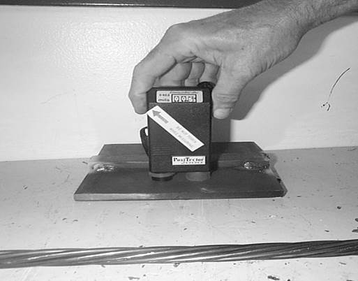
Figure 1. Operation of Film Thickness Gauge
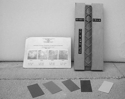
Figure 2. Calibration Standards
 |