SCOPE
This test method describes the procedure for determining the air content of freshly mixed concrete by one form of pressure method.
PROCEDURE
NOTE: Certain coarse aggregates in eastern Iowa with large interconnected pores in the aggregate will cause air meter readings to indicate higher air content than is actually in the concrete because air is compressed in the aggregate pores just as the air is compressed in the paste. An aggregate correction factor must be applied to correct the air content. AASHTO T152 requires an aggregate correction factor for all concrete; however, it typically is not large enough for most aggregates to require adjustment. A list of aggregates that typically require a correction factor is included as well as the procedure to determine aggregate correction factor.
A. Apparatus
1. Measure bowl and cover assembly: All apparatus used shall incorporate the requirements of AASHTO Designation T-152 Section 4, for a Type B Washington-type meter.
2. Tamping Rod: 5/8 in. diameter, having a hemispherical tip.
3. Scoop
4. Strike-off bar
5. Rubber mallet
6. Rubber syringe or polyethylene unitary wash bottle
B. Test Procedure (For use with Washington-Type Air Meter)
NOTE: All meters shall be calibrated annually. Check calibration prior to use on a project and periodically throughout the construction season.
- Calibration of Apparatus
Calibration Canisters (Plug method)
The volume of the calibration canister should be 0.0125 ft3. The effective air volume of the canister depends on the volume of the air meter being calibrated.
Effective Air Volume =100 X 0.0125 ft3/(air meter pot volume)
Below is the effect air volume for the range of meters in service.
|
Air Meter Base Volume |
Effective air volume |
|
|
ft3 |
one canister |
two canisters |
|
0.245 |
5.10% |
10.2% |
|
0.246 |
5.10% |
10.2% |
|
0.247 |
5.05% |
10.1% |
|
0.248 |
5.05% |
10.1% |
|
0.249 |
5.00% |
10.0% |
|
0.250 |
5.00% |
10.0% |
|
0.251 |
5.00% |
10.0% |
|
0.252 |
4.95% |
9.9% |
|
0.253 |
4.95% |
9.9% |
|
0.254 |
4.90% |
9.8% |
|
0.255 |
4.90% |
9.8% |
- Calibration Plug Procedure
a. Fill the air meter with water. The water should be about the same temperature as the air temperature.
Note: Many faucets will mix air into the water. This air can be enough to affect the calibration. In this case, the water should be drawn and left to sit for several hours.
b. Put the lid on and using a plastic bottle provided or a rubber syringe, inject water through one petcock until all the air is expelled through the opposite petcock. Jar the base to insure removal of all air. Leave petcocks open.
c. Stabilize the dial hand at proper initial pressure line by pumping or bleeding off, as needed, while lightly tapping the backside of the dial with the fingers. Inject water through the petcock again to make sure all the air is expelled.
d. Close both petcocks and press down on the thumb lever exhausting air into the base. The dial should read 0.0%. If the dial does not read 0.0%, the test should be repeated. If two or more tests are off by the same amount, a new initial pressure line should be established, and the test repeated to confirm a 0.0% reading.
e. Open the petcocks to relieve the pressure and remove the lid.
f. Make sure the calibration canisters have no water inside and that the bottom hole is clear of debris. Place the canister in the water making sure not to release air from the canister. Repeat step b and c. Close both petcocks and press down on the thumb lever exhausting air into the base. While holding the lever, lightly tap the gage to stabilize the dial reading. The dial should read the effective air volume of the canister (5.0% for air meters with a 0.25 ft3 volume).
g. If the dial reading variation is +/- 0.2% or more from the effective air volume, repeat the test. If the dial reading variation is within +/- 0.2% or less from the effective air volume, the air meter is in proper calibration. To check at 10%, repeat with two calibration canisters. If the dial reading variation is within +/-0.25% (½ scale reading for dials with 0.5% graduations) or less from the effective air volume, the air meter is in proper calibration.
h. If the dial readings are beyond the tolerance for either or both air volumes, the test should be repeated. If after two or more tests, the variation is the same and/or beyond the tolerances, the air meter gauge needs adjustment or replacement. Adjustment of the air meter gauge should only be attempted by trained personnel. For DOT, county, and city owned air meters, the trained personnel include the District Materials staff and the Central Laboratory Testing Support Personnel
See Iowa Test Method 405 for Water Method Calibration
3. Operation of Apparatus (Determination of Air Content of Concrete)
a. Fill the base with a sample of fresh concrete placing the concrete in the base in three equal layers. Rod each layer twenty-five times with the tamping rod provided with the meter. For slumps less than 1 in., the sample may need to be consolidated by internal vibration.
b. Do not allow the rod to forcibly strike the bottom of the base while rodding the bottom layer. For each upper layer, the rod shall penetrate 1 inch into the underlying layer. Care should also be taken to avoid hitting the top edge of the base with the tamping rod.
c. Tap the sides of the base 10-15 times with a rubber mallet after rodding each layer to close the holes left by the rod.
d. A clean, smooth surface on the top edge of the base is necessary to insure a tight seal with the cover. Strike off base, level full, with the straight edge furnished. Wipe the top edge of the base clean to insure a tight seal with the cover.
e. Clamp cover on with petcocks open.
f. With the built in pump, pump air into the air chamber atop the cover until the pressure indicator points to the proper initial pressure line on the gauge. NOTE: The pump stem may need a light coat of oil to slide freely. Too much oil on the stem will fill the pump chamber and block the air valve causing the pump to fail.
g. Using a rubber syringe, inject water through one petcock until all the air is expelled through the opposite petcock. Jar the base to insure removal of all air. Leave petcocks open. NOTE: Use care if injecting water through opposite petcock to not add air bubbles. When jarring the base to remove the air, the base shall not be tilted more than 2 inches from horizontal.
The sequence of Steps f. and g. may be interchanged without adversely affecting the test result.
h. Stabilize dial hand at the proper initial pressure line by pumping or bleeding off, as needed, while lightly tapping the backside of the dial with the fingers. Inject water through the petcock again to make sure all the air is expelled.
i. Close both petcocks. Press down on lever to release air into the base. Tap the sides
of the measuring bowl with the rubber mallet to relieve local constraints. Hold lever down a few seconds lightly tapping the backside of the dial with your fingers until the dial stabilizes. Observe the dial reading before letting up on the lever. Record the dial reading. Report the air content to the nearest 0.1% for air contents up to 8%, or the nearest 1/2 scale division at 8% or higher air content.
j. Open petcocks to release pressure, and then remove cover. Empty the concrete from base, clean up base, cover with petcocks left opened.
4. Determination of Aggregate Correction Factor
a. The aggregate correction factor is determined independently by applying the calibrated pressure to a sample of inundated fine and coarse aggregate in approximately the same moisture condition, amount and proportions occurring in the concrete sample under the test.
b. Calculate the sample weights of the fine and coarse aggregate as follows:
Fs = (S/B) x Fb
Cs = (S/B) x Cb
Where:
Fs = weight of fine aggregate in concrete test sample, lb.
S = volume of measuring bowl, ft3
B = volume of concrete produced per batch, ft3
Fb = weight of fine aggregate in the moisture condition used in batch, lb.
Cs = weight of coarse aggregate in concrete sample under test, lb.
Cb = weight of coarse aggregate in the moisture condition used in batch, lb.
Example of C-3WR Mix
Coarse aggregate wet batch weight = 1597
Fine aggregate wet batch weight = 1421
Container volume = 0.248 ft3
Coarse Aggregate Weight (Cs) = (0.248/27) X 1597 = 14.67 lbs. (6653 grams)
Fine Aggregate Weight (Fs) = (0.248/27) X 1421 = 13.05 lbs. (5920 grams)
c. Mix representative samples of the coarse and fine aggregate, and place in a measuring bowl one-third full of water. Add the mixed aggregate to the bowl, introducing each scoopful in a manner which minimizes entrapped air. If necessary, add additional water to inundate the aggregate. Stir, rod and tap the sides of the bowl to eliminate entrapped air.
d. Soak the aggregate for a time period approximately equal to the amount of time between the introduction of the water into the mixer and the time of performing the test for air content.
e. Follow steps e, f, g, h, and i in paragraph 3. Operation of Apparatus
f. The air content reading is the aggregate correction factor. For ease of determining plastic concrete air in the field, the aggregate correction factor will be rounded down to the nearest 0.5%.
g. Actual concrete air content = Air meter reading - Aggregate correction factor
NOTE: If performing test by removal of a measured amount of water, the inside calibration tube may need to be cut short to prevent drawing sand into the water. When using this method the aggregate correction factor will be the air content reading minus volume of water removed expressed as percent volume of the bowl.
|
|
|
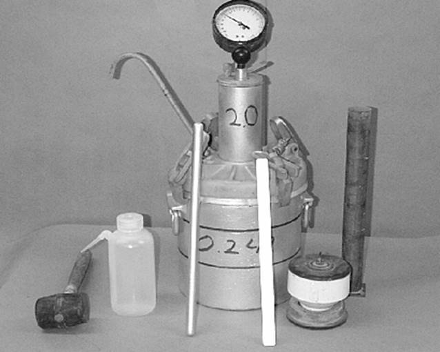
Air Meter and Calibrating Accessories |
NOTE: The following is a list of aggregate sources, including bed numbers, that will typically need an aggregate correction factor applied. When these aggregates are used without an aggregate correction factor applied, excessive bleeding is commonly noted, especially on bridge decks. There is a fairly good correlation of aggregate sources with an Iowa Pore Index primary load greater than 100 may require an aggregate correction factor. Contact the District Materials Engineer when using these aggregates.
|
Source # |
Name |
Beds |
|
A07008 |
Morgan |
5, 9 |
|
A09006 |
Tripoli Platte |
1-5 |
|
A10008 |
Oelwein |
4-5 |
|
A10010 |
Hazelton |
4 |
|
A10016 |
Oelwein #2 |
13-16 |
|
A10030 |
S. Aurora |
1-3 |
|
A16006 |
Stonemill |
4 |
|
A23004 |
Behr |
1-2 |
|
A23006 |
Shaffton |
16-17 |
|
A42002 |
Alden |
0-3, 3 |
|
A44006 |
Leeper |
8-11 |
|
A45008 |
Dotzler |
7-10A |
|
A49020 |
Preston |
7-10 |
|
A49024 |
Maquoketa |
1-8 |
|
A50002 |
Sully Mine |
36-41 |
|
A52004 |
Conklin |
23-24 |
|
A52006 |
Klein |
23-24 |
|
A53002 |
Behrends |
1-5 |
|
A53010 |
Ballou-Olin |
3, 2-3 |
|
A53016 |
Stone City |
2B-3 |
|
A54002 |
Keswick |
13-15 |
|
A57008 |
Bowser-Springville |
6-7, 8-9 |
|
A57018 |
Cedar Rapids |
2-9 |
|
A57028 |
Beverly |
6-7 |
|
A58002 |
Columbus Junction |
16-19 |
|
A63002 |
Durham |
101 |
|
A82002 |
McCausland |
17-19, 1-16 |
|
A89002 |
Douds Mine |
6-13 |
|
A92002 |
Westchester |
14-16 |