This method covers procedures for making, protecting, and curing, according to AASHTO T23. This method also covers testing concrete cylinder specimens for compressive strength, according to AASHTO T22. This test procedure is a supplement and not a replacement for the beam test to determine when a structure may be put in service.
I. MAKING, PROTECTING & CURING SPECIMENS
A. Apparatus for Making Specimens
1. 6 in. x 12 in. or 4 in. x 8 in. steel, brass, or single-use plastic vertical molds meeting the requirements of AASHTO M205.
2. Molds shall be the vertical type.
3. Tamping rods shall comply with AASHTO T23 and the following:
|
Mold Size |
Tamping Rod Diameter |
|
4 in. x 8 in. |
3/8 in. |
|
6 in. x 12 in. |
5/8 in. |
4. Internal or external vibrators may be used. They shall comply with AASHTO T23 with the exception that the diameter of the vibrating element of the internal vibrator shall vary for each specimen size, as stated below. External vibrators shall be either a table type or a plank type.
5. Rubber hammer
6. Wood float or equivalent
B. Making Test Specimens
1. The concrete shall be sampled in accordance with IM 327, Sampling Freshly Mixed Concrete.
2. Before casting specimens, the inside surfaces of the steel or brass molds should be clean and treated with a thin coating of light grease or form oil.
3. Consolidation may be rodding with a tamping rod, or by vibration, either internal or external. Concrete with slump greater than 3 inches shall be consolidated by rodding. Concrete with slump of 1 inch to 3 inches shall be consolidated by rodding or vibration. Concrete with slump of less than 1 inch shall be consolidated by vibration.
a. Rodding. Specimens shall receive the proper number of roddings evenly distributed per layer as indicated in the table. The bottom layer shall be rodded throughout its depth. For each upper layer, the rod shall penetrate 1 inch into the underlying layer. After rodding each layer, the sides and ends of the mold shall be tapped with a rubber hammer until the surface of the concrete is relatively smooth. Use an open hand to tap the single-use molds. After consolidation, strike off the horizontal surface and finish with a float or trowel.
|
Mold Size |
No. of Equal Depth Layers |
No. of Roddings per Layer |
|
4 in. x 8 in. |
2 |
25 |
|
6 in. x 12 in. |
3 |
25 |
b. Internal Vibration. Specimens shall receive the required number of insertions of a vibrator layer as indicated in the table. If more than one insertion is required, distribute the insertion uniformly in each layer. Each layer shall be vibrated only long enough to make the surface relatively smooth. The time required will vary with the consistency of the concrete. Over vibration may cause segregation. In compacting the concrete, the vibrator shall not rest on or touch the sides of the mold. When vibrating the top layer, the element shall penetrate about 1/2 inch into the bottom layer. After vibrating, tap the sides of the mold with a rubber hammer to ensure removal of entrapped air bubbles at the surface of the mold. Use an open hand to tap the single-use molds. When consolidation is complete, strike off and finish with a wood float or trowel.
|
Mold Size |
Vibrator Diameter |
No. of Equal Depth Layers |
No. of Insertions per Layer |
|
4 in. x 8 in. |
¾ to I inch |
2 |
1 |
|
6 in. x 12 in. |
¾ to I 1/2 inch |
2 |
2 |
c. External Vibration. Each layer shall be vibrated only until the surface is relatively smooth. Take care to ensure that the mold is rigidly attached or securely held against the vibrating table or vibrating surface. After consolidation, strike off and finish with a trowel or float.
C. Protecting & Curing
1. Initial Curing. During the first 24 hours after molding, specimens shall be stored under conditions that maintain the temperature immediately adjacent to the specimens in the range of 50°F to 80°F and prevent loss of moisture from the specimens. This may be done by covering specimens with wet burlap and placing a plastic sheet over the burlap, or use other suitable methods to ensure that the foregoing requirements are met. For concrete with minimum specified strength of 6000 psi or greater, initial curing shall be between 68°F and 78°F and maintained in a satisfactory moisture environment. A satisfactory moisture environment may be a bucket with lid filled with lime saturated water to cover the specimens, immediately immersed after molding for up to 48 hours. Or other methods described in AASHTO T 23 may be utilized.
2. Curing to Determine Form Removal Time or When a Structure May be Put in Service. Cure test specimens as nearly as practicable in the same manner as the concrete in the structure. After 48 ± 4 hours, remove specimens from the molds. They shall be stored as near as possible to the point in the structure they represent and shall be afforded the same temperature protection and moisture environment as the structure until the time of testing. Specimens shall be tested while in the moisture condition resulting from the curing they receive.
3. Curing To Check the Adequacy of Laboratory Mix Proportions for Strength or As a Basis For Acceptance or For Quality Control. For this purpose, specimens are to be removed from the molds at the end of 16 to 24 hours and stored in a moist condition at 68°F to 81.5°F until the time of test. For concrete with minimum specified strength of 6000 psi or greater, store in a moist condition at 73.5°F ± 3.5°F until time of test. This condition can be met by immersion in saturated limewater. NOTE: Lime-saturated water is prepared by mixing 0.4 ounces of hydrated lime, with 1 gallon of water. Hydrated lime should be a minimum of 90 percent calcium hydroxide (CaOH).
4. Steam Curing. When artificial heat is used to accelerate curing, concrete specimens shall be placed with the unit being cured and shall receive the same curing as the concrete they represent. Prior to testing the specimens, the temperature of the concrete shall be lowered to the temperature of the surrounding air at a rate not to exceed 40°F per hour.
5. Special care must be given to ensure that specimens are not damaged during handling. For 16 to 24 hours after molding, specimens shall not be moved.
II. TESTING CONCRETE SPECIMENS FOR COMPRESSION
A. Apparatus
1. The testing machine shall conform to AASHTO T22. Manually operated testing machines will be accepted.
B. Time of Testing
1. Make compression tests of moist cured specimens as soon as practicable after removal from curing. Keep specimens moist by use of wet burlap or other suitable covering, which will ensure similar protection until actual time of testing.
2. The time to test specimens otherwise cured will be as directed by the engineer.
C. Test Specimens
1. Neither end of compressive test specimens when tested shall depart from the perpendicularity to the axis by more than 0.5 degrees (approximately 1/8 in. in 12 in.)
2. The ends of the specimens that are not plane within 0.002 in. shall be capped. The planeness of the ends of every tenth specimen should be checked by means of a straightedge and feeler gauge, making a minimum of three measurements on different diameters, to insure that the end surfaces do not depart from a plane by more than 0.002 in.
3. The top surface of vertically cast specimens shall be capped.
D. Capping
1. Capping equipment and procedures shall comply with that described in AASHTO T231.
2. Unbonded caps and equipment shall comply with ASTM C1231.
Unbonded caps are permitted to be used on one or both ends of a cylinder. Neoprene pads used shall meet the requirement listed in the Table 1 of C1231. Pads shall be ½ +1/16 in. thick and diameter shall not be more than 1/16 in. smaller than inside diameter of the retaining ring. Replace pads that do not meet the dimensional requirements or exceed the maximum reuse limits specified in the Table 1 of C1231. Insert pad in the retainer before it is placed on the cylinder.
The height of the retaining ring shall be 1.0 + 0.1 in. The inside diameter of the retaining ring shall not be less than 102 % or greater than 107 % of the diameter of the cylinder. The thickness of the retaining ring shall be at least 0.47 in. for 6 in. diameter retainers and at least 0.35 in. for 4 in. diameter retainers.
E. Test Procedure
1. Placing Specimen
a. Place the plain (lower) bearing block with its hardened face up, on the table or platen of the testing machine directly under the spherically seated (upper) bearing block.
b. Wipe clean the bearing faces of the upper and lower bearing blocks and of the test specimen.
c. Carefully align the axis of the specimen with the center thrust of the spherically seated block.
d. As the spherically seated block is brought to bear on the specimen, rotate its moveable portion gently by hand so that uniform seating is obtained.
2. Rate of Loading
a. Apply the load continuously and without shock. Apply the load at a constant rate within the range of 20 to 50 psi per second. During the application of the first half of the estimated maximum load, a higher rate of loading may be permitted.
b. Do not make any adjustment in the controls of the testing machine while the specimen is yielding, especially in the period just before failure.
c. Increase the load until the specimen yields or fails, and record the maximum load carried by the specimen during test.
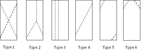
d. Note the type of failure (Figure 1) and the appearance of the concrete if the break appears to be abnormal.
F. Calculations
1. Calculate the compressive strength of the specimen by dividing the maximum load carried by the specimen during the test by the cross sectional area, and express the result to the nearest 10 psi. The attached tables may be used to facilitate these computations.
|
|
|
Figure 1. Compressive Fracture Types |
|
|
|
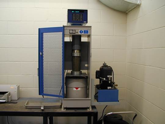
Figure 2. Compression Testing Machine |
|
(Load in Thousands) Table for Computing lb./in.² on 6 in. x 12 in. Cylinders Area = 28.2744 in.² |
|||||||||
|
Load |
Psi |
Load |
Psi |
Load |
Psi |
Load |
Psi |
Load |
Psi |
|
40 |
1410 |
90 |
3180 |
140 |
4950 |
190 |
6720 |
240 |
8490 |
|
41 |
1450 |
91 |
3220 |
141 |
4990 |
191 |
6760 |
241 |
8520 |
|
42 |
1490 |
92 |
3250 |
142 |
5020 |
192 |
6790 |
242 |
8560 |
|
43 |
1520 |
93 |
3290 |
143 |
5060 |
193 |
6830 |
243 |
8590 |
|
44 |
1560 |
94 |
3320 |
144 |
5090 |
194 |
6860 |
244 |
8630 |
|
45 |
1590 |
95 |
3360 |
145 |
5130 |
195 |
6900 |
245 |
8670 |
|
46 |
1630 |
96 |
3400 |
146 |
5160 |
196 |
6930 |
246 |
8700 |
|
47 |
1660 |
97 |
3430 |
147 |
5200 |
197 |
6970 |
247 |
8740 |
|
48 |
1700 |
98 |
3470 |
148 |
5230 |
198 |
7000 |
248 |
8770 |
|
49 |
1730 |
99 |
3500 |
149 |
5270 |
199 |
7040 |
249 |
8810 |
|
|
|
|
|
|
|
|
|
|
|
|
50 |
1770 |
100 |
3540 |
150 |
5310 |
200 |
7070 |
250 |
8840 |
|
51 |
1800 |
101 |
3570 |
151 |
5340 |
201 |
7110 |
251 |
8880 |
|
52 |
1840 |
102 |
3610 |
152 |
5380 |
202 |
7140 |
252 |
8910 |
|
53 |
1870 |
103 |
3640 |
153 |
5410 |
203 |
7180 |
253 |
8950 |
|
54 |
1910 |
104 |
3680 |
154 |
5450 |
204 |
7220 |
254 |
8980 |
|
55 |
1950 |
105 |
3710 |
155 |
5480 |
205 |
7250 |
255 |
9020 |
|
56 |
1980 |
106 |
3750 |
156 |
5520 |
206 |
7290 |
256 |
9050 |
|
57 |
2020 |
107 |
3780 |
157 |
5550 |
207 |
7320 |
257 |
9090 |
|
58 |
2050 |
108 |
3820 |
158 |
5590 |
208 |
7360 |
258 |
9120 |
|
59 |
2090 |
109 |
3860 |
159 |
5620 |
209 |
7390 |
259 |
9160 |
|
|
|
|
|
|
|
|
|
|
|
|
60 |
2120 |
110 |
3890 |
160 |
5660 |
210 |
7430 |
260 |
9200 |
|
61 |
2160 |
111 |
3930 |
161 |
5690 |
211 |
7460 |
261 |
9230 |
|
62 |
2190 |
112 |
3960 |
162 |
5730 |
212 |
7500 |
262 |
9270 |
|
63 |
2230 |
113 |
4000 |
163 |
5760 |
213 |
7530 |
263 |
9300 |
|
64 |
2260 |
114 |
4030 |
164 |
5800 |
214 |
7570 |
264 |
9340 |
|
65 |
2300 |
115 |
4070 |
165 |
5840 |
215 |
7600 |
265 |
9370 |
|
66 |
2330 |
116 |
4100 |
166 |
5870 |
216 |
7640 |
266 |
9410 |
|
67 |
2370 |
117 |
4140 |
167 |
5910 |
217 |
7670 |
267 |
9440 |
|
68 |
2410 |
118 |
4170 |
168 |
5940 |
218 |
7710 |
268 |
9480 |
|
69 |
2440 |
119 |
4210 |
169 |
5980 |
219 |
7750 |
269 |
9510 |
|
|
|
|
|
|
|
|
|
|
|
|
70 |
2480 |
120 |
4240 |
170 |
6010 |
220 |
7780 |
|
|
|
71 |
2510 |
121 |
4280 |
171 |
6050 |
221 |
7820 |
|
|
|
72 |
2550 |
122 |
4310 |
172 |
6080 |
222 |
7850 |
|
|
|
73 |
2580 |
123 |
4350 |
173 |
6120 |
223 |
7890 |
|
|
|
74 |
2620 |
124 |
4390 |
174 |
6150 |
224 |
7920 |
|
|
|
75 |
2650 |
125 |
4420 |
175 |
6190 |
225 |
7960 |
|
|
|
76 |
2690 |
126 |
4460 |
176 |
6220 |
226 |
7990 |
|
|
|
77 |
2720 |
127 |
4490 |
177 |
6260 |
227 |
8030 |
|
|
|
78 |
2760 |
128 |
4530 |
178 |
6300 |
228 |
8060 |
|
|
|
79 |
2790 |
129 |
4560 |
179 |
6330 |
229 |
8100 |
|
|
|
|
|
|
|
|
|
|
|
|
|
|
80 |
2830 |
130 |
4600 |
180 |
6370 |
230 |
8130 |
|
|
|
81 |
2860 |
131 |
4630 |
181 |
6400 |
231 |
8170 |
|
|
|
82 |
2900 |
132 |
4670 |
182 |
6440 |
232 |
8210 |
|
|
|
83 |
2940 |
133 |
4700 |
183 |
6470 |
233 |
8240 |
|
|
|
84 |
2970 |
134 |
4740 |
184 |
6510 |
234 |
8280 |
|
|
|
85 |
3010 |
135 |
4770 |
185 |
6540 |
235 |
8310 |
|
|
|
86 |
3040 |
136 |
4810 |
186 |
6580 |
236 |
8350 |
|
|
|
87 |
3080 |
137 |
4850 |
187 |
6610 |
237 |
8380 |
|
|
|
88 |
3110 |
138 |
4880 |
188 |
6650 |
238 |
8420 |
|
|
|
89 |
3150 |
139 |
4920 |
189 |
6680 |
239 |
8450 |
|
|
(Load in Thousands) Table for Computing lb./in.² on 4 in. x 8 in. Cylinders Area = 12.5666 in.² |
|||||||
|
Load |
Psi |
Load |
Psi |
Load |
Psi |
Load |
Psi |
|
10 |
800 |
50 |
3980 |
90 |
7160 |
130 |
10350 |
|
11 |
880 |
51 |
4060 |
91 |
7240 |
131 |
10420 |
|
12 |
950 |
52 |
4140 |
92 |
7320 |
132 |
10500 |
|
13 |
1030 |
53 |
4220 |
93 |
7400 |
133 |
10580 |
|
14 |
1110 |
54 |
4300 |
94 |
7480 |
134 |
10660 |
|
15 |
1190 |
55 |
4380 |
95 |
7560 |
135 |
10740 |
|
16 |
1270 |
56 |
4460 |
96 |
7640 |
136 |
10820 |
|
17 |
1350 |
57 |
4540 |
97 |
7720 |
137 |
10900 |
|
18 |
1430 |
58 |
4620 |
98 |
7800 |
138 |
10980 |
|
19 |
1510 |
59 |
4700 |
99 |
7880 |
139 |
11060 |
|
|
|
|
|
|
|
|
|
|
20 |
1590 |
60 |
4770 |
100 |
7960 |
140 |
11140 |
|
21 |
1670 |
61 |
4850 |
101 |
8040 |
141 |
11220 |
|
22 |
1750 |
62 |
4930 |
102 |
8120 |
142 |
11300 |
|
23 |
1830 |
63 |
5010 |
103 |
8200 |
143 |
11380 |
|
24 |
1910 |
64 |
5090 |
104 |
8280 |
144 |
11460 |
|
25 |
1990 |
65 |
5170 |
105 |
8360 |
145 |
11540 |
|
26 |
2070 |
66 |
5250 |
106 |
8440 |
146 |
11620 |
|
27 |
2150 |
67 |
5330 |
107 |
8520 |
147 |
11700 |
|
28 |
2230 |
68 |
5410 |
108 |
8590 |
148 |
11780 |
|
29 |
2310 |
69 |
5490 |
109 |
8670 |
149 |
11860 |
|
|
|
|
|
|
|
|
|
|
30 |
2390 |
70 |
5570 |
110 |
8750 |
150 |
11940 |
|
31 |
2470 |
71 |
5650 |
111 |
8830 |
151 |
12020 |
|
32 |
2550 |
72 |
5730 |
112 |
8910 |
152 |
12100 |
|
33 |
2630 |
73 |
5810 |
113 |
8990 |
153 |
12180 |
|
34 |
2710 |
74 |
5890 |
114 |
9070 |
154 |
12260 |
|
35 |
2790 |
75 |
5970 |
115 |
9150 |
155 |
12330 |
|
36 |
2860 |
76 |
6050 |
116 |
9230 |
156 |
12410 |
|
37 |
2940 |
77 |
6130 |
117 |
9310 |
157 |
12490 |
|
38 |
3020 |
78 |
6210 |
118 |
9390 |
158 |
12570 |
|
39 |
3100 |
79 |
6290 |
119 |
9470 |
159 |
12650 |
|
|
|
|
|
|
|
|
|
|
40 |
3180 |
80 |
6370 |
120 |
9550 |
160 |
12730 |
|
41 |
3260 |
81 |
6450 |
121 |
9630 |
161 |
12810 |
|
42 |
3340 |
82 |
6530 |
122 |
9710 |
162 |
12890 |
|
43 |
3420 |
83 |
6610 |
123 |
9790 |
163 |
12970 |
|
44 |
3500 |
84 |
6680 |
124 |
9870 |
164 |
13050 |
|
45 |
3580 |
85 |
6760 |
125 |
9950 |
165 |
13130 |
|
46 |
3660 |
86 |
6840 |
126 |
10030 |
166 |
13210 |
|
47 |
3740 |
87 |
6920 |
127 |
10110 |
167 |
13290 |
|
48 |
3820 |
88 |
7000 |
128 |
10190 |
168 |
13370 |
|
49 |
3900 |
89 |
7080 |
129 |
10270 |
169 |
13450 |