SCOPE
This test method covers the determination of the maximum and minimum-index dry densities of cohesionless, free-draining soils using a vibratory table. This method is based on ASTM D4253 and D4254.
This test method is applicable to soils that contain up to 15%, by dry weight, of soil particles passing a No. 200 sieve. Further, this test method is applicable to soils in which 100%, by dry weight, of soil particles pass a ¾-in. sieve. If soil contains particles greater than ¾-in, screen the sample over the ¾-in. sieve and replace the aggregate retained with an equal weight of No. 4 to ¾-in. aggregate from the same source, or break up the material larger than ¾-in. and return it to the sample.
The maximum index density of a free-draining soil is determined by placing either oven-dried or wet soil in a mold, applying a surcharge (dead weight) to the surface of the soil, and then vertically vibrating the mold, soil, and surcharge.
PROCEDURE
A. Apparatus
1. Electromagnetic Vibrating Table – A steel table with a vertically vibrating cushioned steel deck generally about 30 by 30 in. mounted to a concrete floor. The table shall be capable of vertically vibrating the mold assembly at an average double amplitude (peak-to-peak displacement) of 0.013 ± 0.002 in. at a frequency of 60 Hz or 0.019 ± 0.003 in. at 50 Hz under test conditions.
2. Cylindrical metal mold having a nominal volume of 0.100 ft3. The actual volume of the mold used should be within ±1.5% of the specified nominal volume.
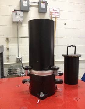
3. Surcharge weight and surcharge base plate – Total weight of surcharge base plate and surcharge weight of 56.5 ± 0.5 lb. Base plate diameter of 5 15/16 in. The vibrating table, mold and surcharge weight are shown in Figure 1.
4. Surcharge Base-Plate Handle – A device used to place and remove the surcharge base plate.
5. Digital or Dial-Indicator Gage- A device installed in the guide brackets, to measure the difference in elevation between the rim of the mold and top of the surcharge base plate after vibration. The dial indicator shall have a minimum of 2-in. capacity, with a readability of 0.001-in.
6. Scale capable of weighing at least 15,000 grams and sensitive to 1 gram.
7. Drying oven capable of maintaining a temperature of 230 ± 9°F.
8. A rigid steel straight edge, 9-in. long, with one beveled cutting edge.
9. Hoist – A rope, chain, or cable hoist of at least 310 lb capacity for lowering the surcharge weight.
10. Pouring Devices – Two pouring spouts are required, one having an inside spout diameter of 0.50 in. for soils with 100% passing the No. 4 sieve and another with an inside spout diameter of 1.0 in. for soils with 100% passing the 3/8” sieve.
11. Calibration Bar, metal, about 3 by 12 by ¼ in., optional.
12. Other equipment such as mixing pans, a large metal scoop, a hair-bristled dusting brush, and a timing device indicating minutes and seconds, a micrometer with at least a 1-in. capacity with 0.001-in. readability.
B. Calibration
See Appendix A.
C. Sample Preparation
1. Obtain a sample of about 25 lb. Before testing, the sample being tested should be stored to prevent freezing, contamination, loss of soil, or loss of identification.
2. If the “dry method” is being performed for the maximum-index density, the representative test sample needs to be dried in a drying oven to a constant weight.
3. After drying, break up any particles that stuck together during the drying process but avoid breaking the natural size of the particles.
D. Minimum-Index Density Test Procedure
1. Mix the oven-dried test sample to have an even distribution of particle sizes. If a pouring device is used, place the soil as loosely as possible in the mold. Hold the pouring device upright and vertical. Continuously adjust the height of the pouring device to maintain a free fall of the soil of about ½ in. Move the pouring device in a spiral path from the outside to the center of the mold to form each layer of nearly uniform thickness. Spiraling motion should be just sufficient to minimize particle segregation. If a scoop is used, place the soil as loosely as possible by holding the scoop or shovel just above the soil surface to cause the material to slide rather than fall onto the previously placed soil.
2. Fill the mold approximately ½ inch to 1 inch above the top of the mold.
3. Trim off the excess soil level with a straightedge. Be careful when trimming to avoid excessively disturbing the soil surface and causing rearrangement and settlement of the soil particles. Make one continuous pass with the straightedge, or two passes if necessary.
4. Determine and record the weight of the mold plus soil.
5. Calculate the minimum-index density, ρdmin.
![]()
Where:
![]() Minimum- index
density,
Minimum- index
density, ![]()
Ms = Weight of the tested-dry soil, lb.
![]()
![]() Calibrated
volume of mold, 0.100
Calibrated
volume of mold, 0.100 ![]()
E. Maximum-Index Density Test Procedure (Dry Method)
1. Use the same sample in the mold that was used to determine the minimum-index density.
2. Attach the mold to the vibrating table, tighten the nuts and make sure that the mold is free of any movement.
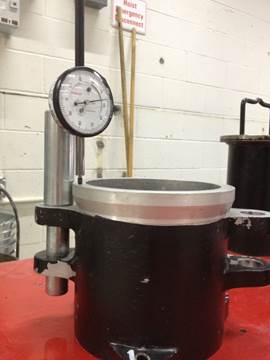
3. Obtain the value of Initial Dial Reading, Ri, as shown in Figure 2:
a. Insert the dial indicator gage holder in each of the guide brackets with the dial gage stem in contact with the rim of the mold (at its center) on both sides of the guide brackets.
b. Obtain six sets of dial indicator readings, three on each side of each guide bracket. The average of these six readings is the initial dial gage reading (Ri), Record Ri to the nearest 0.001 in.
4. After the Ri is obtained, remove the dial gauge from the guide sleeves.
5. Attach the guide sleeve to the mold, and attach the mold to the vibrating table.
6. Place the surcharge base plate (twist the plate several times). Remove the surcharge base plate handle.
7. Lower the surcharge weight on top of the surcharge base plate. The surcharge weight should be lowered as carefully as possible to prevent any compaction before vibration takes place. Make sure that the mold and guide sleeve are free of any movement.
8. Set the vibrator control (rheostat) so the mold assembly being used achieves a double amplitude of vertical vibration of 0.013 ± 0.002 in. at 60 Hz or 0.019 ± 0.003 in. at 50 Hz.
9. Vibrate the mold and test specimen for 8 ± ¼ minutes at 60 ± 2 Hz or for 12 ± ¼ minutes at 50 ± 2 Hz.
10. After vibration, remove the surcharge weight and guide sleeve from the mold. Check that the surcharge base plate is firmly and uniformly in contact with the surface of the soil. If the surcharge plate wobbles, this should be noted on the report form.
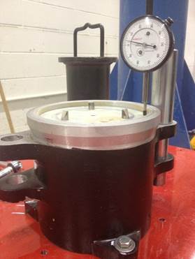
11. Place the dial gauge indicator in each of the guide brackets, obtain and record three dial gauge readings (Rf) on opposite sides of the surcharge base plate and average (see Figure 3). Brush aside any fines that might have collected on the surcharge base plate where these readings will be taken.
12. Remove the surcharge base plate from the mold and detach the mold from the vibratory table. Prevent any fines on the surface of the surcharge base plate and the rim of the mold from entering the mold. If the weight of the fines is greater than about 0.2 % of the total weight of the test specimen, determine the weight and note it on the report form.
13. Determine and record the weight of the mold and soil.
14. Calculate the maximum-index density, ρdmax.
![]()
Where:
![]() Maximum-index
density,
Maximum-index
density, ![]()
Ms = Weight of the tested-dry soil, lb.
![]()
![]() Volume of
tested dry soil,
Volume of
tested dry soil, ![]()
![]()
![]() Calibrated
volume of mold, 0.100 ft3
Calibrated
volume of mold, 0.100 ft3
![]() Calibrated
cross sectional area of mold,
Calibrated
cross sectional area of mold, ![]()
![]()
d
= Diameter of mold, ![]()
![]() Positive
difference in elevation between the top surface of the mold and tested soil,
Positive
difference in elevation between the top surface of the mold and tested soil, ![]()
![]()
![]() Initial dial
gauge reading,
Initial dial
gauge reading, ![]()
![]() Average of
final dial gauge readings on opposite sides of surcharge base plate after the
vibration period,
Average of
final dial gauge readings on opposite sides of surcharge base plate after the
vibration period, ![]()
![]() Thickness of
surcharge base plate,
Thickness of
surcharge base plate, ![]()
F. Maximum-Index Density Test Procedure (Wet Method)
1. The wet method test can be done on either oven-dried soil to which sufficient water is added, or on wet soil from the field. Mix the test sample and make sure to have an even distribution of particle sizes and water content with as little segregation as possible. If water is added to an oven-dried soil, allow a minimum soaking period of ½ hour. The amount of water added should be sufficient enough that free water does not accumulate in the mixing pan.
2. Attach the mold to the vibrating table.
3. With the vibrating table turned on, slowly fill the mold with wet soil using a scoop. After each increment of soil is added, inspect to see if a small amount of free water has accumulated on the soil surface. If not, add a sufficient amount of water by squeezing from a sponge, pouring from a small container, or by other means. During this process, which is to take 5 to 6 minutes, the vibration must be adjusted to prevent excessive boiling and fluffing of the soil. During the final minute of vibration, any water above the surface of the soil should be removed using means which prevent the removal of soil.
4. Obtain the initial dial reading (Ri) as stated in the Dry Method, Step 3. After the Ri is obtained, remove the dial gauge from the guide sleeves.
5. Assemble the surcharge base plate, surcharge weight, and guide sleeve as specified in the Dry Method, Steps 5 to 7.
6. Vibrate the mold assembly and specimen as specified in the Dry Method, Steps 8 and 9.
7. Remove the surcharge weight and guide sleeve from the mold.
8. Remove any free water appearing above, on, and around the surcharge base plate.
9. Obtain and record final dial indicator gage readings (Rf) as specified in the Dry Method, Step 11.
10. Remove the surcharge base plate and detach the mold from the vibratory table. Determine and record the weight of the mold and soil. Carefully remove the entire wet specimen from the mold and place it in a pan of known weight for oven drying. Wash all particles clinging to the inside of the mold and bottom of the base plate into the pan.
11. Dry the specimen in a drying oven. Determine and record its oven-dried weight.
12. Calculate the maximum-index density, ρdmax.
![]()
Where:
![]() Maximum-index
density,
Maximum-index
density, ![]()
Ms = Weight of the oven-dried soil, lb.
![]()
![]() Volume of
tested soil,
Volume of
tested soil, ![]()
![]()
![]() Calibrated
volume of mold,
Calibrated
volume of mold, ![]()
![]() Calibrated
cross sectional area of mold,
Calibrated
cross sectional area of mold, ![]()
![]()
d = Diameter of mold, in
![]() Positive
difference in elevation between the top surface of the mold and tested soil,
Positive
difference in elevation between the top surface of the mold and tested soil, ![]()
![]()
![]() Initial dial
gauge reading,
Initial dial
gauge reading, ![]()
![]() Average of
final dial gauge readings on opposite sides of surcharge base plate after
the vibration period,
Average of
final dial gauge readings on opposite sides of surcharge base plate after
the vibration period, ![]()
![]() Thickness of
surcharge base plate,
Thickness of
surcharge base plate, ![]()
Note: If it is established that the wet method produces a maximum–index density higher than the dry method and this higher value would significantly affect its application, then the result of the wet method should be used.
G. Relative Density
1. Relative density of a field soil, Dd, can be defined using dry density measured in the field, ρd, through a ratio that involves maximum and minimum-index densities of the soil.
![]()
Where:
Dd= Relative Density, %
![]() =Field Density,
=Field Density, ![]()
2. Conversely, the required field dry density, ρd, can be calculated if a relative density requirement is provided by the contract documents.

Where:
Dd= Relative Density, %
![]() =Field Density,
=Field Density, ![]()
|
|
|
|
Figure 1: Vibratory Table, Mold, and Surcharge Weight |
Figure 2: Initial Dial Reading, Ri |
|
|
|
|
Figure 3: Final Dial Reading, Rf |
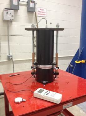
Figure 4: Accelerometer Testing the Amplitude of the Table |
CALIBRATION OF VIBRATORY TABLE
The vibratory table, mold and surcharge weight are shown in Figure 3.
The vibratory table should be calibrated before the first use and annually. It should also be calibrated after any repairs that take place or when the results are questionable. The calibration procedure is listed below.
1. Check the mold diameter (6.00 ± 0.01 in.), and the height (6.10 ± 0.01 in.).
2. Check the volume of the mold (0.10 ft3 ± 0.0015 ft3). The volume of the mold can be calculated using the direct measurement method or the water filling method.
3. Vibrating Table, with and without the mold, needs to have a double amplitude of 0.013 ± 0.002 in. at 60 Hz or 0.019 ± 0.003 in. at 50 Hz when vibrating (see Figure 4).
a. A vibratory meter can be used to determine the amplitude of the table by means of peak acceleration as follows:
![]()
Where:
A
= Nominal peak acceleration in g (where g = 386.088 ![]() )
)
Y = Amplitude of vertical vibration, in.
f = frequency in cycles per second, Hz.
b. Or by means of peak velocity.
![]()
Where:
Y= double amplitude of vertical vibration, in.
V=peak velocity, in./sec.
f=frequency in cycles per second, Hz.
If the table by itself and/or the table plus mold are not producing the required double amplitude of 0.013 ± 0.002 in. at 60 Hz or 0.019 ± 0.003 in. at 50 Hz when vibrating, adjust the min and max pucks inside the rheostat control box and re-test again as described above. If after re-testing, the vibrating table is not producing the required double amplitude, contact the manufacturer.