9.20 PAVEMENT JOINTS
Joints are established in PCC pavements to prevent random cracking and to provide areas for pavement to expand and contract. These joints are often cleaned and sealed with various types of sealants to keep out water and incompressible such as soil, sand, and gravel. The specifications for each type of joint are detailed in Road Standard PV-101.
In multi-lane construction, it is important that jointing be reviewed and discussed prior to the start of paving operations. Jointing in multi-lane construction can be very difficult, especially when intakes and utility accesses are present. It is very important to establish correct jointing within the first pass of multi-lane paving to ensure correct joint alignment in future, adjacent lanes of pavement.
9.21 JOINT SAWING
Refer to Road Standard PV-101 for details of the saw cut required for each type of joint.
For transverse joints on a conventional pavement slab, the saw cut should be stopped before the blade reaches the edge of the slab. The joint opening at the surface of the pavement should come within an inch of the edge of the pavement. By stopping shy of the edge, there is less chance of the saw “blowing out” a spall on the edge of the slab. This is particularly important when using early entry saws as the blade on an early entry saw rotates upward at the cutting face, increasing the risk of a blown-out edge. This also prevents the joint sealant from running down the face of the pavement.
9.22 CLEANING JOINTS
The Project Engineer must ensure adequate inspection of joint cleaning operations prior to sealing. Specification 2301.03, P discusses proper method of cleaning joints.
9.23 FILLING SAWED JOINTS
Specification Section 4136 lists the joint sealant material to be used in various types of joints. All joints are to be filled before any traffic, including construction traffic, is permitted on pavement. Often construction traffic has been allowed on unsealed pavements or the contractor has not kept the pavement surface cleaned of construction debris or spilled aggregate. The construction traffic has then forced foreign materials into the unfilled sawcut, which can create joint spalls. Pavement joints should be reviewed to determine if spalls are occurring. When spalls occur, they should be repaired. If the spall is small enough, correction can consist of removing the spalled material and filling the joint with joint sealant material. Large spalls should be repaired by an epoxy mixture or a partial depth patch depending on their severity.
Joint Filling
Due to pavement crown, hot poured asphaltic joint material sometimes flows out of the joint leaving an opening below the pavement surface which allows entrance of sand and dirt into the joint opening. This will cause spalling of joint edges when pavement expands. To ensure a properly filled joint across the entire pavement width, the
Contractor is required to stop the saw cut ½” to ¾” from the edge of pavement. This helps to prevent sealant from flowing out of the joint opening. Refer to Standard Road Plan PV-101 for appropriate joint edge treatments.
All joint sealant materials should be placed so that the top edge is from 1/8 to 3/8 inch below the pavement surface. Excessive filling of joints can result in excessive sealant material being forced out of the joint and soiling the pavement surface.
Excess sealant material should be removed from the pavement surface prior to project acceptance.
Sealing Equipment
Hot poured asphaltic joint material can be overheated in hot pour kettles. An overheated sealant has lost its elasticity and will prematurely fail. Tiny bubbles appearing on the surface of the sealant after it is placed in the joint can be an indication of overheating. Thermometers on hot pour kettles need to be checked and replaced if necessary. Calibrated thermometers are available from the Construction and Materials Bureau (515-239-1352) to use in checking contractor’s thermometers.
Backer Rod
While backer rod is no longer specified for new construction, it may be required for refilling of joints in existing PCC pavements. Backer rod is approved on a brand name basis. Approved backer rods are found in Materials I.M. 436.04. To monitor manufacturer quality control, a 1 to 2 feet long piece of backer rod may be sampled from each project and sent to the Construction and Materials Bureau.
9.25 CD, ED, EE & EF JOINTS, AND OTHER DOWELED SUPPORT ASSEMBLIES
To ensure that a doweled contraction joint will function as designed, it is critical that the assembly be properly installed. Dowel bars provide load transfer across the joint without prohibiting the opening and closing of the joint during temperature changes of the pavement.
Expansion Joints
Cross‑sectional shapes of preformed joint material different than the shape shown on Standard Road Plan PV-101 are available. These may also be used with Project Engineer approval. For pavements thinner than 8 inches in depth, joint material may need to be shortened appropriately. Material should be removed from the bottom side only to fit thinner pavement sections. For thicker pavement sections, additional expansion joint material may be added to the bottom of the joint to achieve the correct total joint depth.
For expansion joints that extend through a curb section, install preformed joint material the full width of pavement through the curb. Do not attempt to bend material to fit the shape of the curb. The opening in curb section above the top surface of the joint material may be filled in with a solid piece of joint material cut to the same shape as the curb.
Bond Breakers
Specification 4151 requires smooth dowel bars to be coated with a bituminous or paraffin-based bond breaker prior to delivery to a project. A bond breaker is necessary to prevent concrete from adhering to the dowel bars which could lead to locking of the joint and possible random cracking.
Often dowel assemblies are fabricated several months before they are incorporated into a project. The assemblies are then delivered to, and stored on, the project site, and the bond breaker becomes weathered. Bituminous bond breakers are especially susceptible to weathering.
Prior to being incorporated into a project, dowel assemblies should be inspected to ensure that the bond breaker is in good condition. If the bond breaker is cracked, dry or has a weathered appearance, steps should be taken to ensure that the dowels are adequately coated to prevent bonding with concrete. With approval of the Project Engineer, any of the following procedures may be followed to reestablish a bond breaking coating:
n Return dowel assemblies to the fabricator to be recoated.
n Apply grease over weathered coatings.
n Apply form oil over weathered coatings.
Note: Form oil may wash away during a rain event. Dowel assemblies should be recoated if a rain event occurs after application of form oil and before paving.
Dowel Tolerances
To permit pavement slabs to move longitudinally on the subgrade during expansion and contraction, dowels must be parallel to both centerline and the surface of the pavement. Specification 2301.03, E discusses dowel placement tolerances. Dowel assemblies should not be permitted to remain in place if wire supports cannot hold dowels in correct alignment.
Dowel Assembly Placement
When placing assemblies on subgrade, contractors use the bottom support wires of the assembly to serve as a guide for bar alignment. This is not objectionable provided the bars are fabricated at proper angle to the wire supports. Assemblies should be inspected for proper fabrication when delivered to the project.
Contractors shall not be permitted to block up or support the assemblies to obtain proper height of dowel bars. When a paving project has two different slab thicknesses requiring load transfer devices, the Contractor shall furnish correct height basket dowel assemblies specifically fabricated to position bars at mid‑depth of the slab for each slab thickness.
At the Contractor’s option, the temporary wire fasteners, which hold some assemblies together for shipping, may or may not be cut after installation and prior to paving. This applies to baskets fabricated in accordance with the PV-101 Road Standard with only three properly sized tie wires per basket. Often baskets are fabricated with additional tie wires to ensure stability of the basket when handling and placing. This is an acceptable practice as long as the tie wires in excess of the 3 required are cut prior to paving. The Contractor is responsible to ensure both proper alignment of the bars and the prevention of random cracks. Therefore, the decision as to whether to cut or not cut the wire fasteners should be made with the goal of preventing both misalignment and random cracks.
Check for movement of assemblies during passage of the slipform paver. If properly set, side forms of the paver should not contact with the ends of wire bar supports. Check to ensure vibrators on the paver or finishing equipment are set to proper height so vibrators do not touch steel during passage over assemblies.
Workers who position steel and vibrate concrete must not step on joint assemblies. Assemblies must be firmly anchored to subgrade or subbase with a minimum of eight stakes per lane width (Standard Road Plan PV-101) to resist horizontal and vertical movement during concrete placement and subsequent finishing operations.
Marking Joint Locations
Prior to paving, a point or line representing the midpoint of the dowels in an assembly must be marked on granular subbase, or subgrade so an accurate saw cut location can be made on the cured pavement. One method is to spray paint a line on the subbase or subgrade at the midpoint of dowels in a line, projected from the proposed saw cut. This band of paint must be kept as narrow as possible to minimize chance of error in correctly locating the saw cut. An alternate method would be to place a dowel basket staking pin on either side of pad line, in line with the midpoint of the dowels, which will be used as a reference.
Dowel midpoint markings should then be transferred to the concrete surface. This may be accomplished with a string line marking plastic concrete or by use of a chalk line after concrete has hardened. This should ensure that the transverse joint will be sawn over the center of the dowel bar basket assembly. Do not permit the saw operator to “eyeball” joint sawing from one edge of slab to the other.
Blanking Bands
Specification 2301.03H, 3 requires a blanking band be used to blank out the transverse texture over the center of the dowel assemblies. Care needs to be taken to ensure that the blanking band is correctly located over the center of dowel assemblies. Using a blanking band will ensure a smooth, nontextured pavement surface at midpoint on the dowel assembly. When longitudinal texturing is used, no blanking band is required.
9.26 LONGITUDINAL JOINT DESIGN
Project plans include joint layout sheets that show location and type of joints to be constructed within pavement structure. The joint layout designs for paving plans have specific requirements for certain type joints which consider traffic movements during and after construction and effect of joint type on these traffic movements.
Joints should be constructed as shown on plans, unless the Standard Road Plans allow for alternates. Any requests by the Contractor for joint substitution should be submitted to the Construction and Materials Bureau for review.
The Standard Road Plans show the required joint dimensions for the various types of pavement joints. It should be noted for longitudinal joints that only a single T/3 depth sawcut is shown.
Standard Road Plan PV-101 details the different types of longitudinal joints. This Standard Road Plan discusses the only joint types that may be interchanged. All other joints shall be constructed as shown on the plans.
The KT-2 and KT-3 joints include both a keyway and a tie bar to hold two adjacent lanes together. It is the combination of the keyway and tie bars that provides proper load transfer between adjacent pavement lanes. It is important to check that the proper sizes of keyway and tie bars are being provided to ensure proper performance of the joint. Keyway and tie bar sizes are shown on Standard Road Plan PV-101. The end of the bar that is placed in the concrete during the first pass shows an optional bent detail. This detail is included to support the end of the bar on the subgrade when it is placed in the plastic concrete. An alternate support would be to place the horizontal bar on a chair in the plastic concrete. Supporting the end of the bar with a shovelful of plastic concrete or a rock will not ensure that the tie steel remains horizontal during its passage through the slipform paver. This practice should not be allowed.
Tie Bar Placement
Because the steel placed in L and KT joints is intended to hold two adjacent lanes together, it is very important that the bars be placed in a manner that will assure that they will perform as intended. The most important aspect of placing tie steel reinforcement is to ensure that the concrete is consolidated around the bar after being placed so that adequate pull-out strength is achieved to resist the tendency for the two pavement sections to pull away from each other over time. Whether the bars are straight or bent, or placed by a mechanical inserter or by hand, the concrete must be consolidated around the bar to ensure proper anchorage of the bar in the hardened concrete.
Typically steel for L joints is inserted by mechanical methods in front of the finishing machine or directly behind the vibrators and in front of the pan on the finishing machine when using slip form placement methods. This is an acceptable practice and achieves the desired result since the finishing machine imparts vibration into the pavement through the pan which consolidates the concrete around the bar.
When placing steel for KT joints, contractors often insert the steel through a side form on the finishing machine when slip form placement methods are used. Other methods have included use of formed steel keyway slipped through the side form of the finishing machine from front to back. Either method is an acceptable practice as the concrete is consolidated around the bars either through vibration imparted into the mix from the side forms or the vibrators themselves.
Tie steel should not be inserted behind the finishing machine by mechanical or hand methods without consolidation of the concrete around the bar.
9.27 LONGITUDINAL JOINT (L JOINT) TIE‑STEEL INSPECTION
All paving contractors should place “L” joint tie steel according to details in Standard Road Plan PV-101.
Procedure
The following “L” joint tie‑steel inspection procedures will be required on all paving projects where centerline or lane line tie steel is either manually or mechanically placed in plastic concrete:
n Manually check location and depth of “L” joint tie steel in the plastic concrete behind slipform paver each day
n Using a magnetic locator (pin finder), verify location of “L” joint tie steel in hardened concrete every day
Frequency
To ensure compliance with proper joint design parameters, use the following minimum frequencies:
n Once in morning and once in afternoon for tangent roadway sections
n In at least three locations within all horizontal curve sections. These locations generally would be in beginning transition, in middle of curve, and in ending transition.
n For each inspection, at least two tie‑steel locations within a panel should be checked.
n Checks of any area with out‑of‑tolerance “L” joint tie steel should be expanded so that extent of problem area is identified for retrofit correction. These areas should be determined on hardened concrete.
The checked areas of hardened concrete should not overlap previously checked plastic concrete areas.
Documentation
· Project inspector should document tie‑steel inspection results in field book. In addition, any areas with out‑of‑tolerance tie steel should be shown in remarks area of PCC Plant Page (Form 800240E).
Tolerance
Minimum placement tolerances for purpose of initiating retrofit correction only are as follows:
n Depth: D/2 +1 inch, -1 1/2 inches
n Angle: Minor variations to 90 degrees not critical as long as at least an effective length of 12 inches of tie steel extends across joint
n Lateral Position & Number: The following minimum number of bars should extend at least a nominal 12 inches across joint:
a. The centerline L‑1 and L‑2 joints and any lane line joint of multilane pavements
should have a minimum of:
· 6 bars per 17 -foot panel for all pavement 8 inches or greater in design thickness. The Construction and Materials Bureau will evaluate any areas greater than 100 feet in length that have 5 bars or less per panel.
b. L‑3 joint deficiencies in lateral position and number should be evaluated by the Construction and Materials Bureau.
Out-of-Tolerance
If previously mentioned inspection procedures discover out‑of‑tolerance tie steel, the Contractor has the following options to remedy the problem:
n Contractor may substitute a longer bar to better ensure an adequate length across joint.
n Contractor may place additional uniformly spaced bars across joint to better ensure proper number across joint
n Contractor may move bar inserter uphill on paver.
Contractors may do any combination of these remedies, at their own expense, to avoid retrofitting tie steel. Any remedies described above shall be approved by the Project Engineer.
After two days of inadequate correction procedures, the Contractor will be required to use positive placement procedures (basket assemblies or bar supports) for remaining "L" joint tie‑steel areas on project.
The Construction and Materials Bureau should be immediately informed of any tie‑steel placement problems.
Retrofit
If a project is determined to have out‑of‑tolerance tie steel according to previously mentioned guidelines, the Contractor is required to suggest a tie‑steel retrofit procedure. All retrofit corrections shall include replacing tie steel such that the final retrofit panel has the required number of bars per panel as shown on Standard Road Plan PV-101. Prior to correction, the Project Engineer shall submit the Contractor's retrofit correction procedure to the Construction and Materials Bureau for approval. The contractor may suggest retrofit correction by any method, such as bar‑in‑slot or the cross‑stitch procedure described as follows:
Drill a 7/8-inch diameter hole transversely across the joint at an angle and distance as described in Table 9.5.1. A drilling guide shall be used to ensure the angle and distance are correct and consistent. Use care not to drill completely through the slab, leaving approximately 1 inch undrilled at the bottom of the slab. This ensures the epoxy grout will be contained in the hole when backfilling. Figure 9.27.1 provides a cross sectional view of drilling into the slab.
Figure 9.27.1
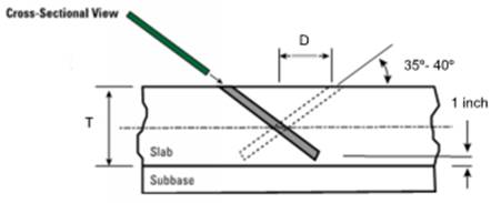
Use a low impact hydraulic drill. If a hydraulic drill is not available, then a predrill hole with a smaller drill bit followed by a larger pneumatic drill at the lowest setting can be used. Care must be taken not to damage the surface or crack the concrete when drilling. The process should be demonstrated prior to use on the repair pavement. Drill holes on alternating sides of the joint line at designed tie‑steel spacing, taking care to avoid any in‑place bars. Maintain a distance of at least 15 inches from load transfer devices.
Blow air into holes to remove dust and debris. The air must be free of oil and other contaminants. Pour the epoxy into the hole, leaving some volume for the bar to occupy the hole. Insert a 0.75 inch (#6) deformed epoxy bar into the hole, remove excess epoxy and finish flush with the pavement surface. Approximately 1 inch of cover is provided at the surface of the slab when using the dimensions in Table 9.2.1. Epoxy grout shall meet requirements of Materials I.M. 491.11, Appendix A. Pavement can be opened to construction or public traffic when the epoxy grout is tack free.
Table 9.27.1
|
Slab Thickness (T) inches |
|||||
|
8 |
9 |
10 |
11 |
12 |
|
|
Distance from Joint to Hole (D) inches |
|||||
|
35º |
5.75 |
6.50 |
7.25 |
7.75 |
8.50 |
|
40º |
- |
- |
- |
6.50 |
7.25 |
|
Length of Bar (inches) |
|||||
|
35º |
9.50 |
11.00 |
12.50 |
14.50 |
16.00 |
|
40º |
- |
- |
- |
12.50 |
14.00 |
|
Diameter of Bar (inches) |
|||||
|
All |
0.75 |
0.75 |
0.75 |
0.75 |
0.75 |
Price Adjustments
In addition to the retrofits required above, all areas of pavement with out‑of‑tolerance tie steel shall be price adjusted according to Construction Manual 2.53.