PRECAST & PRESTRESSED CONCRETE BRIDGE UNITS
GENERAL
The purpose of this Instructional Memorandum is to set forth the minimum requirements of the fabricator’s Quality Control Program for the fabrication and inspection of precast/prestressed concrete bridge units.
SCOPE
To ensure that all work performed will be in accordance with the contract documents by establishing management commitment to quality control, with trained, qualified, certified personnel and uniform production procedures.
FABRICATOR APPROVAL
In order to furnish precast/prestressed bridge units to projects administered by the Iowa Department of Transportation, the fabricator shall be placed on the approved producer/fabricator list (Appendix A) prior to the letting.
1. Each fabricator must submit a written application to the respective District Materials Engineer (DME). This application shall detail the fabricator’s Quality Control Program. NOTE: Fabricators with operations in more than one District shall apply to the appropriate DME for each site. (A sample application is attached to this IM.)
2. Each fabricator/producer shall have a plant specific Quality Control Procedure Manual modeled and detailed in accordance with the “Guidelines” for the fabrication of precast/prestressed bridge units intended for use on state, county and/or city projects.
Guidelines of quality control for the fabrication of precast/prestressed bridge units are listed in Appendix F of this IM.
These guidelines are considered the principal factors in quality control and are the basis upon which each plant-specific procedure manual will be accepted and/or rejected. The plant-specific procedure manual shall detail fabrication procedures such as but not limited to: description of production lines, calculation procedure, tensioning procedures, concrete mixtures, approved mix designs, concrete placement and consolidation, detentioning procedures, curing procedures, repair and finishing procedures, handling, storage and shipping procedures. A sample of the forms used by the fabricator to document plant quality control inspection shall be approved by the DME and be included in the manual. A copy of this manual shall be submitted to the Iowa Department of Transportation for approval by the DME and the Prestressed & Precast Concrete Engineer.
3. The fabricator shall have a sufficient number of qualified, certified, capable personnel to perform the necessary quality control functions. This includes, but is not limited to, activities such as ensuring proper placement of steel reinforcement, placement and tensioning of strand, material identification and handling, concrete proportioning, mixing and consolidation, fabrication, marking, curing, and documentation. The quality control personnel shall be responsible for all phases of fabrication, for units being produced for state, county, and/or city projects.
4. Safety: To assure safety, the fabricator shall have a safety policy, safety program, safety manual and a designated safety officer responsible for enforcing the safety rules. Additionally, each fabricator shall comply with all applicable laws, rules, regulations and ordinances governing safety. The fabricator shall make adequate provisions satisfactory to the DME for the safety of the inspector, particularly at all sampling, tensioning and inspection locations. Any violation of the Safety Laws, Rules or Regulations may be considered sufficient grounds by the DME for suspending all inspection activities.
QUALITY CONTROL PROGRAM
The fabricator’s written application shall detail the following:
1. A flowchart listing the chain-of-command to aid in problem solving and to facilitate communication between the Iowa DOT inspector and appropriate fabricator personnel. Included in the flowchart shall be a statement of management commitment to, and responsibility for, maintaining the Quality Control Program.
a. Quality control inspections shall be performed by QC and/or by personnel other than those responsible for production and thus, reporting directly to management.
b. Deviations from the established flowchart, in personnel that will affect the Quality Control Program, require prior approval from the DME (i.e., situations involving the temporary absence of personnel normally responsible for quality control inspection).
2. A statement that the fabricator will maintain qualified (certified) personnel.
3. Designation of how specification requirements are relayed to the responsible quality control personnel and which company representative is responsible for this task.
4. A statement that the approved plant-specific procedural manual will be adhered to maintained and updated as needed.
CONDITIONAL STATUS
Non-compliance of the fabricator written Quality Control Program will constitute grounds for the DME to place the fabricator on conditional status. The DME will document and submit a written notice to the fabricator identifying the areas of non-compliance. Continued non-compliance will be considered grounds to remove the producer from the approved list.
Conditional status may be rescinded by the DME if the fabricator provides a written description of corrective measures taken to resolve the issue(s) to the DME. An appeal may be made to the Review Board if the fabricator wishes to contest the conditional status. The Review Board will meet as needed for disciplinary actions and appeals involving approved producers.
Iowa DOT inspection of fabrication will be suspended until the conditional status is rescinded by the DME or the Review Board resolves the issue(s). Products manufactured during the suspension will not be approved for use on projects.
The Review Board will consist of the Iowa DOT Materials Engineer, the Iowa DOT Prestressed & Precast Concrete Engineer, and the Chief Structural Design Engineer.
Failure to remedy the issues that constituted the conditional status, or repeated placement on conditional status (three instances during a three-year period) will require an automatic review by the Review Board to consider disciplinary measures. Willful misrepresentation by the fabricator or intentional shipment of non-approved products shall also be grounds for removal from the approved fabricator list.
Any fabricator removed from the list may be considered for reinstatement by reapplying to the appropriate DME and the Review Board.
CERTIFIED PRECAST/PRESTRESSED PERSONNEL
The Iowa DOT Office of Materials shall certify inspectors and Quality Control Technicians responsible for the inspection of precast/prestressed concrete bridge units.
Certification requirements are as follows:
1. Successful completion of the Iowa DOT training course (a score of at least 80% on the written test).
2. Experience of forty hours (of a variety of prestress work) assisting in quality control inspection at an approved plant. NOTE: The required forty hours must be documented and approved by the DME. A sample of Prestress Work History (40 hours) Form is attached to this IM.
Certification will be valid for a five-year period, after which the technician will retest to maintain certification.
The Quality Control Technician will be appointed by the producer and will be responsible for the quality control process and testing at each plant. The Quality Control Technician will have the following:
1. Knowledge of the plans, shop drawings and specification requirements.
2. Knowledge of the product manufacturing operations.
3. A valid DOT Level I PCC Certification or ACI Level I Certification.
If technicians perform aggregate gradation, they shall possess an Aggregate Level II Certification.
CERTIFICATION
Upon successfully completing the requirements for certification, the Program Director will issue a certificate and a pocket certification card. This certification is not transferable.
PERFORMANCE REQUIREMENTS
A written notice may be issued to the certified technician for any inadequacies performed during their duties. Upon receipt of two such notices, the certified technician may be given a three-month suspension. After three written notices, the certified technician is subject to decertification.
DECERTIFICATION
The certificate will become invalid for reasons such as:
1. Failure of the certificate holder to renew the certificate prior to regular expiration described above.
2. False or fraudulent use of information to secure or renew the certificate.
3. False or fraudulent actions or documentation by the certificate holder.
4. Not performing tests and technicians duties properly and in accordance to specification.
RENEWAL OF CERTIFICATION
Certifications will remain valid for five years (a three-month grace period will be allowed). If the individual has not renewed their certification within the 90-day grace period, she/he will be automatically decertified. The individual may obtain certification by taking the examination. If the individual does not take the examination within one year from the date of decertification, he/she must retake all applicable schools and pass the examinations. The responsibility for applying for recertification shall rest with the certified individual.
It shall be the responsibility of the individual to inform the Office of Materials of any address change.
Retesting will be required every five years regardless of work experience or performance. Failure of any certification test shall require the applicant to retake the applicable school and pass the test.
Detailed information on certification, desertification, and recertification is located in IM 213.
PREFABRICATION MEETING
The fabricator shall initiate this meeting prior to the commencement of any fabrication. Representatives of both the fabricating plant and the DOT shall attend this meeting.
Items to be discussed are:
· Production schedule
· Applicable specifications, IMs, shop drawings, and design standards
· Approved mix designs
· Methods of testing and curing
· Materials testing, acceptance, and approval
· Material storage and handling
· Quality Control Program and certification requirements
· Fabrication errors, discrepancies, and repair methods
· Acceptance and approval of final products
· Methods of measuring camber
· Cylinder strength requirements
· Final inspection and camber reading
· Shipping procedure and protection
· Documentation of the prefabrication meeting
· Combined pours with altered strand design patterns or with multiple size differentials must have prior approval of the contracting authority, and shall be in compliance with the requirements and provisions of Appendix E.
By mutual agreement, periodic scheduled meetings between the fabricator and the District Materials Engineer may be used in lieu of the prefabrication meeting.
MATERIAL APPROVAL, CERTIFICATIONS & SAMPLING FREQUENCY
All materials for use in precast/prestressed concrete fabrication shall meet the requirements of the Standard Specifications and the IMs.
· Cement - Cement shall be from an approved source (listed in IM 401, Appendix A) and shall meet the requirements of Section 4101 of the Standard Specifications. Monitor samples shall be at the rate of one sample per month per supplier.
· Fly Ash - Fly Ash shall be from an approved source (listed in IM 491.17, Appendix A) and shall meet the requirements of Section 4108 of the Standard Specifications. Monitor samples shall be at the rate of one sample per month per supplier.
· Ground Granulated Blast Furnace Slag (GGBFS) - Ground Granulated Blast Furnace Slag shall be from an approved source (listed in IM 491.14, Appendix A) and shall meet the requirements of Section 4108 of the Standard Specifications. Monitor samples shall be at the rate of one sample per month per supplier.
· Concrete – Same mix shall be used on all beams in an individual span (camber issue) and in all exterior beams (color issue)
- Self consolidating concrete, if used shall meet the requirements of IM 445 Appendix D.
· Fine Aggregate - Fine Aggregate shall be from an approved source and shall meet the requirements of Section 4110 of the Standard Specifications. The fabricator shall perform certified gradation testing at a minimum frequency of one test per week per source.
· Coarse Aggregate - Coarse Aggregate shall meet the requirements of Section 4115 of the Standard Specifications, and shall be Class III durability aggregate. The fabricator shall perform certified gradation testing at a minimum frequency of one test per week per source.
· Admixtures - Admixtures shall be from an approved source and shall meet the requirements of Section 4103 of the Standard Specifications.
· Steel and Iron Products – All reinforcing steel, iron products, and coatings that will be incorporated in the final product shall be domestic origin and shall be melted and manufactured in the USA.
· Strand for Prestressing - Strand for prestressing shall be from a domestic source and shall be the size, grade, and type specified in the contract documents. The fabricator shall provide certified Mill Test Reports and load-elongation curves. Prestressed strand may be accepted by certification, and monitored by sampling and testing at the rate of one sample per heat. Sample size is 6 ft. (2m) length of strand with copies of certified Mill Test Reports. All strands shall be free of contamination (dirt, mud, oil, paint, wax, etc.) that may prevent bonding between the strands and the concrete. Strands shall be free from nicks, kinks, and excessive rust. Rusting is generally acceptable if the rust is light and if pitting is not evident. Strand shall conform to the requirements of AASHTO M203 M (ASTM A416, Grade 270, ASTM A416M, Grade 1860), seven-wire prestressing strand.
· Wire Failure-Prestressing Strands-During stressing of seven-wire prestressing strands for a single beam or one line of beams cast with a common strands, the number of individual wire failure shall not exceed 2% of the total number of wires. The permissible number of wire failure shall be rounded to the next lowest whole number. No individual strand shall have more than one wire failure.
Example - LXD 100, No. of 7-wire strands = 36, total number of wires = 252, 2% of total number of wires = 5.04, max allowable No. of strands with one wire failure = 5.
· Uncoated Reinforcement - Steel reinforcement for precasting/prestressing shall be grade 60 (ASTM A615) and shall be from an approved source and shall be accompanied by a Mill Test Certification and shall comply with the requirements of Section 4151.03 of the Standard Specifications. Monitor sampling will be done at a minimum rate of one sample of the most common bar per manufacturer per year. Rusting is generally acceptable if the rust is light and if pitting is not evident.
· Epoxy-Coated Steel Reinforcement for precasting/prestressing shall meet the requirements of ASTM A615, Grade 60, IM 451.03B, Article 4151.03B of the Standard Specifications and the following requirements:
- Epoxy coated steel shall be from an approved source and an approved coater.
- Epoxy coated steel shall be accompanied by a Mill Test Certification and Certified Coating Report.
- Assurance verification, sampling and testing shall be performed at the fabrication plant by the Iowa DOT QA Inspector. Frequency of sampling and testing shall be a project-by-project basis and shall include and not be limited to the following:
a. Measurement of epoxy coating thickness (acceptance)
b. Visual observation of the coated bars and stirrups for uniform coating and cracking (verification)
The QA Inspector shall submit one sample of coated bar and stirrup for testing by Central Laboratory at a frequency of one sample per size, per year, per manufacturer (coater).
- Epoxy coated steel shall be properly identified.
5. Epoxy coated steel shall remain bundled and tagged until immediately before it is to be incorporated into the beam or the precast items. NOTE: Leftovers or remnants of epoxy steel shall be properly identified, stored, protected and traced to original Mill Test Report or an invoice or to a bill of lading in order to be accepted.
6. Epoxy coated reinforcement should be protected from sunlight and weather exposure and long-term storage should be avoided.
· Sole Plates, Steel & Masonry Curved Sole Plates - Acceptance shall be on the basis of approved shop drawings, acceptable workmanship, and fabrication inspection reports which shall include mill certification, type and steel grade, and galvanizing checks. ASTM A852, Grade 70 is required. ASTM A514, Grade B or ASTM A709, Grade 70W structural steel may be substituted for ASTM A852, Grade 70.
· Protection Plates - Acceptance shall be on the basis of approved shop drawings, and acceptable workmanship. Protection plates can be used at the discretion of the producer/fabricator. Protection Plates shall be made of ASTM A36 and shall be fully galvanized in accordance with the requirements of ASTM A153, Class B.
· Inserts/Hangers – Acceptance shall be on the basis of approved shop drawings, which shall include the manufacturer’s design, spacing and installation requirements. Inserts/hangers can be used in prestressed beams (1) upon request by the contractor as an aid to stripping floor forms, (2) shall be coated using one of the following methods:
§ Electroplating in accordance with ASTM B633, service condition SC4, required coating thickness of 1.0 mil. Classification and coating suffix FE / Zn 25
§ Mechanical galvanizing in accordance with ASTM B695, Type 1, Class 50. Minimum coating thickness shall be 2 mils.
· Neoprene Bearing Pads - Neoprene bearing pads will be accepted from an approved manufacturer on the basis of certification with monitor sampling and testing in accordance with IM 495.03 and Article 4195.02 of the Standard Specifications.
· Coil Ties and Hold Downs - Will be sampled once per year per size.
· Water - Water shall meet the requirements of Article 4102.01 and will be sampled once per year.
· A copy of reports of approved materials, cement certifications, Mill Test Reports for steel reinforcement, etc., shall be kept on file by the fabricator and be available for examination by the engineer for one calendar year after the prestressed units are incorporated into a project.
EQUIPMENT & PLANT APPROVAL
· An independent registered professional engineer shall design casting beds and approve the equipment. The design shall be stamped, approved and signed by the registered professional engineer who designed the casting beds. Annual safety inspection to verify the adequacy of the bed(s) (vertical movement) shall be performed and documented by the producer. A copy of the safety inspection shall be submitted to the State of Iowa upon request. Calculation shall be submitted to the Iowa Department of Transportation should there be any anticipated change(s) in the maximum intended loading.
· Plan dimensions and specification values are to be considered as the target value to strive for and comply with as the design value from which deviations (within tolerances) are allowed. If any plan or specification changes are implemented, then the revised values shall govern.
· Casting beds, forms and bulkheads shall meet the requirements of Article 2407.03 of the Standard Specifications. Casting beds shall be checked for line and grade at a frequency of at least once per year or as often as necessary. This check shall be performed and documented by the fabricator. Casting beds, forms, and bulkheads that are not mortar tight shall be sealed or repaired prior to reuse.
· Forms shall be straight and true to the line. Form joints shall be comparable and even with each other.
· Weighing and proportioning equipment shall meet the requirements of Article 2001.20 of the Standard Specifications except that a vibrator will not be required on the cement batch hopper. Batching and proportioning equipment and scales shall be calibrated at least once a year. The Engineer may order a verification calibration test or check as necessary to ensure continued compliance.
· Mixing equipment shall meet the requirements of Article 2001.21 of the Standard Specifications.
· Stressing equipment shall be in accordance with Article 2407.03.A.3 of the Standard Specifications and shall be calibrated at a frequency of at least once per year or when is determined necessary. Calibration of the jacking system shall compare the indicated force applied by the system, to the force indicated on a calibrated load cell, dynamometer, or proving ring.
· When artificial heat is used to obtain temperatures above 100°F (38°C), the temperature of the interior of the concrete shall be recorded by a system meeting the requirements of Article 2407.03.D of the Standard Specifications.
· Concrete temperature shall be uniform throughout the curing process and shall not vary by more than 40°F (22°C) through the entire casting bed. Temperature probe locations shall be randomly located within 100 ft. throughout the length of the line (each line).
· Concrete shall not be placed without the written permission of the engineer when:
a. Ambient temperature is below 35°F (2°C)(Article 2407.03.C)
b. Plant approval by the engineer is required for cold weather placement.
· Automatic moisture measuring-equipment for aggregate shall comply with the requirements of IM 527.
· Testing equipment shall have sufficient capacity for the testing involved. Cylinder breaking equipment shall be calibrated at a minimum frequency of once per year.
· Jack calibration/tensioning equipment calibration shall be performed by an independent certified, approved laboratory and witnessed by Iowa DOT.
· Plant calibration shall be performed once a year and/or as needed by an independent certified, approved laboratory and witnessed by Iowa DOT.
DOT INSPECTOR KNOWLEDGE & DUTIES
The inspector's main functions are to monitor production, report findings and assist in quality improvement wherever possible. This is done to ensure that the Quality Control Program provided by the fabricator is functioning and is adequate to produce acceptable products.
The inspector is the liaison between the contracting authority and the fabricator. Good communications are important to maintain a good working relationship between the inspector and fabricator.
The inspector should be familiar with Standard Specification Article 1105.07, which describes the authority and duties of the inspector. He/she will not direct the fabricator's activities, but will have the authority and responsibility to question and, where necessary, reject any operation not in accordance with contract documents.
There are many phases included in the process of fabricating precast prestressed concrete products. While all phases are important to the overall quality of the product, there are several that the Agency inspector should make every effort to personally witness or perform:
· Verify tensioning calculations and tensioning production records as soon as possible after tensioning.
· Visually inspecting the product as soon as possible after casting.
· Approve repairs.
· Provide final inspection after repair and finish work is completed including excessive lateral sweep.
· Review fabricator’s documentation and prepare fabrication report.
An Iowa DOT inspector shall monitor the remaining phases as needed (as deemed necessary by the District Materials Engineer).
· Location of hold-ups and hold-downs, strand pattern, bed condition
· Placement of end plates, trueness of forms, insert type and location
· Tensioning operations
· Steel reinforcement and placement
· Concrete placement, making strength specimens, concrete operations
· Curing operation
· Compressive strength determination
· Detensioning operations
· Camber at release
· Finishing and repair operations
· Storage of units
· Loading and transporting (Overhang requirements; padding required if chains used for tie-downs.)
MINIMUM QUALITY CONTROL DUTIES BY THE FABRICATOR
The Quality Control Technician shall check and document the following:
PRE-POUR
· Identify and document materials requiring outside fabrication inspection.
· Identify potential fabrication or production problems and notify Iowa DOT inspectors.
· Verify that all materials incorporated meet the requirements of the contract documents.
· Review concrete placement documents for strand locations.
· Check tension calculations.
· Measure elongation and gauge pressure during tensioning.
· Check hold-down and insert locations.
· Check stress distributions.
· Check steel placement.
· Check strand position.
· Check condition of pallet (level, holes, gaps, and other deformities).
· Determine moisture of aggregates.
· Check form condition and placement (oil, line alignment level, and tightness)
CONCRETE PLACEMENT
· Check on use of an approved mix design and batching operations (sequence).
· Ensure appropriate placement and proper vibration techniques.
· Measure and record concrete temperature.
· Ensure test cylinders are properly made.
· Ensure test cylinders are properly cured.
· Ensure appropriate finish.
· Ensure appropriate curing operations.
POST-POUR
· Check temperature and record during curing process.
· Ensure concrete strength has been met prior to releasing the line.
· Ensure proper detensioning procedure.
· Check unit for defects and obtain approval for repairs.
· Identify and store cylinders with the respective units.
· Check beam ends for fabrication in accordance with the plans.
· Ensure exterior sides of facia beams are grouted.
· Measure and record overall dimensions of beam.
· Measure and record camber at release and compare to design camber. (See camber measurement procedures on page 12.)
· Check and measure camber for compliance before shipping.
· Check and/or measure and record lateral sweep before shipping. (For sweep correction, refer to page 15 of this IM.)
· Ensure proper cylinder cure. (Cylinders must remain moist throughout the entire cure process and until testing.)
CONCRETE STRENGTH
1. For release strength, see the requirements of Article 2407.03 of the Standard Specifications and/or as indicated on the plans.
2. For 28-day strength, see the requirements of Article 2407.03 of the Standard Specifications and/or as indicated on the plans.
3. Prestress units cannot be shipped until the 28-day strength is attained.
4. Beams must be at least 28 days old before the floor is placed, unless a shorter curing time is pre-approved by the engineer.
5. For each release and shipping strength a set of three (3) cylinders representing three different portions of the line cast (each end and the center) shall be cast. The average of three (3) cylinders shall be used to determine the minimum strength requirements for either release or shipping.
For either release or shipping strengths the set of cylinders tested shall meet the following requirements:
a. The average strength of the specimens tested shall be equal to or greater than the minimum strength required.
b. No individual cylinder of the set tested shall have a compressive strength less than 95% of the specified strength.
c. If both conditions a. & b. are not met after the appropriate curing period, another set of specimens representing the line shall be tested.
6. Concrete strength specimens shall receive the same curing as the cast units. Curing can be accomplished by either steam-cure or sure-cure systems.
REPAIR, FINISH, HANDLING & STORAGE
· Honeycomb and surface defects (exterior and interior beams) shall be filled and finished in accordance with the requirements of Article 2407.03.L of the Specifications. Bugholes smaller than 1/2 in. (12.7 mm) in diameter need not to be filled unless it’s in a concentrated form. NOTE: For definition of honeycomb, bug holes and surface defects please refer to Appendix G of this IM.
· Handling and storage shall be done in accordance with the requirements of Article 2407.03.K of the Standard Specifications.
· Each unit must have legible identification (displayed on the web). Identification shall include the following: producer’s name, beam number, fabrication date and facia girder identification.
· The top of each beam will have a tined finish (grooves), except for a smooth strip, approximately two inches wide, continuously along one side of the beam. Grooves will be 1/4 inch in depth, spaced at not more than one inch center to center and will have a width of 1/8-inch ± 1/16-inch.
· The stenciled word “EXTERIOR” shall be printed in red-colored ink at each end of the exterior face of the facia girder. The stenciled letters of the word ”EXTERIOR” shall be three (3) inches in height and be visible.
· Prestressed/Precast units shall be free from honeycomb, surface defects, surface voids, bug holes and oil stain. Bug holes can be accepted if they are less than 1/2” in diameter (as measured by a DOT template) and not in a concentrated form (shot gun appearance).
· The outer surface of “Exterior Girders” shall have a surface finish in accordance with the requirement of Article 2407.03.L of the Standard Specifications. The finished surfaces shall be free of surface defects, oil stain and shall have a uniform color.
· When required by the plans, beam-ends shall be coated and sealed at the prestressed fabrication plant with an approved gray or clear epoxy listed in IM 491.19, Appendix B.
· NOTE: Prestressed/precast units shall be stamped and accepted by the QA inspector prior to shipping. Prestressed/precast units that are not stamped and accepted by the QA Inspector shall be rejected at the project site and cannot be incorporated into the project.
· The overhang shall not exceed 5 percent of the length of the beam and/or as indicated in the following table:
For LXD beams over 95 ft. (28.96 m) in length, use the following table as specification limitations on shipping overhang:
|
Beam |
Required Minimum Strength at Shipping (PSI) |
Maximum Overhang Length in Feet |
|
LXD 100 |
7500 |
12 |
|
” |
6000* |
9 |
|
LXD 105 |
7500 |
12 |
|
“ |
7000 |
10 |
|
“ |
6000* |
5 |
|
LXD 110 |
7500 |
14 |
|
“ |
7000* |
12 |
|
LXD 115 |
7500* |
14 |
|
LXD 120 |
7500* |
14 |
*Plan specified minimum 28-day compressive strength.
Please note, as indicated, the table includes the maximum shipping overhang for the longer LXD beams, which are not specified in the notes on standard LXD beam detail sheets. Also please note this table applies to standard beams using standard strand patterns. The Office of Bridges and Structures shall review all non-standard beams and structures to determine the maximum allowable shipping overhang. The standard LXD beam sheets will be revised to include all of this information.
The concrete strength shall be determined by the appropriate cylinder test or any other approved methods. The concrete strength required for some shipping overhangs may exceed the plan-specified minimum 28-day concrete compressive strengths.
CAMBER MEASUREMENT PROCEDURE
· Camber due to prestress shall be measured while the beam is on the bed by checking the beam profile immediately (within three hours) after detensioning and separation of the beam.
· Camber shall be measured from the pallet to the bottom of the beam at mid-point utilizing a conventional tape measure. Camber shall be measured and recorded to the nearest 1/8 inch. Beam shall be resting free on the pallet at the time of the camber measurement. Camber acceptance shall be achieved prior to shipping.
· Noncompliant camber of any beam shall be verified at a later date. Beams cannot be accepted without a compliant camber and specific approval of the engineer.
SWEEP MEASUREMENT PROCEDURES
1. Sweep shall be measured when the beam is not influenced by any differences in surface temperatures from face-to-face or side-to-side.
2. A beam should be able to meet the sweep tolerance without any external influence (temperature, sun) or any applied force of any kind.
3. The determination of sweep compliance shall be made no earlier than 48 hours and not until after the sweep correction techniques have been fully completed and the beam has been freed. The corrected beam must remain straight, in straight line parallel to the centerline of the beam and must comply with specification requirements of L/80 (2407.03.J.2). For sweep determination, beam must be completely free. If the beam is checked on the bed, lifting and resetting shall be required.
NOTE: “L” is the entire beam length in feet (meters).
SWEEP/EXCESSIVE SWEEP HANDLING PROCEDURES
The following procedures shall be followed in the event of prestressed concrete beams having developed sweep in excess of the allowable specification requirement tolerance of L/80. The procedures described in this section apply only to a uniform sweep with single lateral curvature producing a maximum offset at mid-point of the beam length.
A. Beams with excessive sweep greater than L/80 shall be corrected at the fabricator’s plant prior to shipping to the project site.
B. The fabricator may either tilt or lean the beam. This procedure will not require any prior approval.
C. A force may be applied to induce a maximum corrective lateral deflection as outlined below:
Beam Type and Size (English) Sweep (inches)
LXC 55 - LXC 80 L/80
LXD 80 - LXD 105 3L/160
LXD 110 - LXD 120 L/40
Beam Type and Size (Metric) Sweep (mm)
C 17 M - C 24 M L
D 24 M - D 32 M 1.5L
D 33 M - D 36 M 2L
This procedure will not require any prior approval.
D. If a force is to be applied other than what is outlined in paragraph “C”, then this force needs to be predetermined and pre-approved by the Office of Bridges and Structures.
E. If approved, the intended force indicator must be carefully applied and must be monitored by means of a dial or a digital gauge. The monitor inspector shall make sure that the applied force does not exceed the predetermined limits. If the force exceeds the predetermined limits, then the beam shall be rejected.
F. A beam with twisted upper flange or lower flange shall not be accepted.
G. If approval is required for the jacking force, a written request shall be made to the District Materials Engineer. The District Materials Engineer will forward to the Office of Bridges and Structures for review and approval and with a copy to Central Materials.
H. Sweep in prestressed beam shall be measured at the web mid-point utilizing a cotton or nylon string tied to beam ends with sufficient tension. A conventional tape measure or a ruler may be used to measure the sweep.
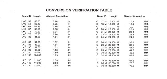
*For further information, consult the “Sweep Correction/Conversion Verification Table,” listed below.
Sweep Correction
Sweep Correction - Field Procedures
For Beams that have developed sweep at the project site, a correction procedure may be applied to correct the sweep. A force may be applied to induce a maximum corrective lateral deflection within the following limits:
Beam Type and Size (English) Sweep (inches)
LXC 55 - LXC 80 L/80
LXD 80 - 105 3L/160
LXD 110 - 120 L/40
Beam Type and Size (Metric) Sweep (mm)
C 17 M – C 24 M L
D 24 M – D 32 M 1.5L
D 33 M – D 36 M 2L
· L is the entire beam length in feet (meters).
· This procedure does not require prior approval, if the force to be applied does not exceed the predetermined limits provided in the above outline. The 48-hour monitoring period identified in Paragraph F for the determination of sweep compliance shall not be required.
· If the force to be applied is greater than the limits outlined above then the intended applied force shall be predetermined and preapproved by the Office of Bridges and Structures.
· If approved, the intended force shall be carefully applied and shall be monitored by means of a dial indicator or a digital gauge. The monitor inspector shall make sure that the applied force does not exceed the predetermined limits. If the applied force exceeds the predetermined limits, then the beam shall be rejected.
· The 48-hour waiting period requirements identified in Paragraph “F” shall be required.
· Sweep determination and acceptance at the project site shall be measured along a chord line at mid-point of the top flange. A conventional tape measure or a ruler may be used to measure the sweep.
*For further information, consult the “Sweep Correction/Conversion Verification Table listed on page 15 of this IM.
DOCUMENTATION
Production records shall include as a minimum, the following data for each precast or prestress unit:
· Approved mix used
· Tensioning calculation
· Elongation measurements and gauge pressure
· Air temperature, at time of concrete placement
· Concrete temperature
· Curing temperature
· Release and shipping cylinder strengths
· Release and 28-day or shipping camber
· Fabrication Approval Date
· Dimensional check
· General appearance
· Repairs made
· Irregularities and remarks
REPORTING
The units are to be reported on Form #820905.
SHIPPING & ACCEPTANCE
Units shall be in full compliance with the specification requirements at the time of shipment to the project. Units shall be inspected and stamped before leaving the fabricator yard.
Final acceptance of the units shall be at the project site by construction personnel.
PRECAST & PRESTRESSED CONCRETE BRIDGE UNITS
FABRICATOR APPROVAL APPLICATION
|
1. Has a current Plant Procedures Manual been approved by the DME? (Yes or no. If no, please explain.) |
|||||||||
|
|
|||||||||
|
|
|||||||||
|
2. I agree to the following statements: Production operations will adhere to the Plant Procedures Manual. Updates and changes will be approved by the DME before use. (Yes or no. If no, please explain.) |
|||||||||
|
|
|||||||||
|
|
|||||||||
|
3. Will Plant Quality Control forms be maintained during the course of production and be available for review by Iowa DOT personnel? (Yes or no. If no, please explain.) |
|||||||||
|
|
|||||||||
|
|
|||||||||
|
4. Which company representative (position or name) will be responsible for distributing current, applicable specifications to production and quality control personnel? |
|||||||||
|
|
|||||||||
|
|
|||||||||
|
5. Do quality control personnel inspect all phases of manufacturing (i.e., materials used, mixes, tensioning, pouring, curing, finishing, yardage and shipping)? (Yes or no. If no, please explain.) |
|||||||||
|
|
|||||||||
|
|
|||||||||
|
6. Are the personnel responsible for quality control inspection Iowa DOT-certified? (Yes or no. If no, please explain.) |
|||||||||
|
|
|||||||||
|
|
|||||||||
|
7. Please attach a flowchart of your company chain of command (See attached example.) including names, business addresses and phone numbers of appropriate management personnel to contact for problem resolution. |
|||||||||
|
|
|||||||||
|
Indicate the District(s) for which you are seeking approval below. |
|||||||||
|
1 |
2 |
3 |
4 |
5 |
6 |
||||
|
|
|||||||||
|
Authorized Company Signature |
|
Date |
|
||||||
|
DME Recommendations |
|||||||||
|
|
|||||||||
|
|
|||||||||
|
DME Signature |
|
Date |
|
||||||
|
|
|||||||||
|
Approval (Yes or No) Remarks |
|
||||||||
|
|
|||||||||
|
|
|||||||||
|
Materials Engineer Signature |
|
Date |
|
||||||
|
|
|||||||||
TECHINICAL TRAINING & CERTIFICATION PROGRAM
PRESTRESS WORK HISTORY
|
NAME |
|
||||||||||||||||
|
ADDRESS |
|
||||||||||||||||
|
CITY |
|
STATE |
|
ZIP CODE |
|
||||||||||||
|
CERTIFICATION NO. |
|
ACI NO. |
|
(If not Level I PCC) |
|||||||||||||
|
|
|||||||||||||||||
|
WORK HISTORY |
|||||||||||||||||
|
LOCATION OF PLANT |
|
||||||||||||||||
|
DUTIES PERFORMED: |
DATE |
HOURS |
|||||||||||||||
|
|
|
|
|
|
|||||||||||||
|
|
|
|
|
|
|||||||||||||
|
|
|
|
|
|
|||||||||||||
|
|
|
|
|
|
|||||||||||||
|
|
|
|
|
|
|||||||||||||
|
|
|
|
|
|
|||||||||||||
|
|
|
|
|
|
|||||||||||||
|
|
|
|
|
|
|||||||||||||
|
SUPERVISOR (Certified Prestress Technician) |
|
||||||||||||||||
|
COMPANY or AGENCY |
|
||||||||||||||||
|
REMARKS: |
|
||||||||||||||||
|
|
|||||||||||||||||
|
|
|||||||||||||||||
|
|
|||||||||||||||||
|
|
|||||||||||||||||
|
|
|||||||||||||||||
|
|
|||||||||||||||||
PLEASE FORWARD TO DISTRICT MATERIALS ENGINEER