AGGREGATE PROPORTIONING GUIDE
FOR PC CONCRETE PAVEMENT
GENERAL
This Instructional Memorandum covers procedures for developing a well-graded aggregate combination for use in Portland Cement Concrete paving. It is the responsibility of the mix designer to design a mix with appropriate properties for the intended application and placement method. The mixture should be economical, meet workability and finishing requirements, and allow for a proper air void system at a minimum water/cementitious ratio. Regardless of how the mix performs in controlled conditions, ultimately it must be evaluated on how well it performs during production and placement in the field.
Concrete mixtures produced with a well-graded aggregate combination tend to reduce the need for water, provide and maintain adequate workability, require minimal finishing, and consolidate without segregation. These characteristics tend to enhance placement properties as well as strength and long-term performance. Concrete mixtures produced with a gap graded aggregate combination tend to segregate easily, contain higher amounts of fines, require more water, and increase susceptibility to shrinkage. These characteristics tend to limit placement properties as well as strength and long term performance.
Achieving a uniform gradation may require the use of three or more different aggregate sizes. It is the responsibility of the mix designer to consider particle shape when designing a mix. When using the coarseness/workability chart it is assumed that particles are rounded or cubical shaped. Rounded or cubical shaped aggregates typically enhance workability and finishing characteristics. Flat and elongated aggregates typically limit workability and finishing characteristics.
COARSENESS/WORKABILITY
CHART*
*Shilstone, J. Sr., ”Concrete Mixture Optimization”, Concrete International, June 1990
The mathematically combined gradation, expressed as percent retained, shall be calculated in accordance with IM 531. The coarseness and workability factors shall be calculated and then plotted in a coarseness/workability chart as shown in Figure 1.
![]()
Workability Factor = Combined % Passing No. 8 (2.36 mm) Sieve*
*The workability factor shall be increased by 2.5% for each increase of 94 pounds of cement over 564 pounds per cubic yard.
Shilstone recommends a target of 60 Coarseness Factor and 35 Workability Factor. For a nominal maximum aggregate size of 1 in. to 1 1/2 in. (25 mm to 37.5 mm), Shilstone recommends a Workability Factor of 34 to 38 when the Coarseness Factor is 52 and a Workability Factor of 32 to 36 when the Coarseness Factor is 68.
Aggregate blends that plot close to the bottom boundary line may tend to have too much coarse aggregate. Aggregate blends with a point below the bottom boundary line (Zone V) will produce rocky mixtures with inadequate mortar and shall not be allowed.
Aggregate blends above the top boundary line (Zone IV) will produce sandy mixtures with high amounts of fines requiring higher water contents and potential for segregation.
Aggregate blends with coarseness factors higher than 75 (Zone I) will produce gap graded mixtures with inadequate workability and high potential for segregation.
Aggregate blends with a point in Zone III, respectively, corresponds with Zone II for aggregate sizes less than 1/2 in. (12.5 mm).
0.45 POWER CURVE
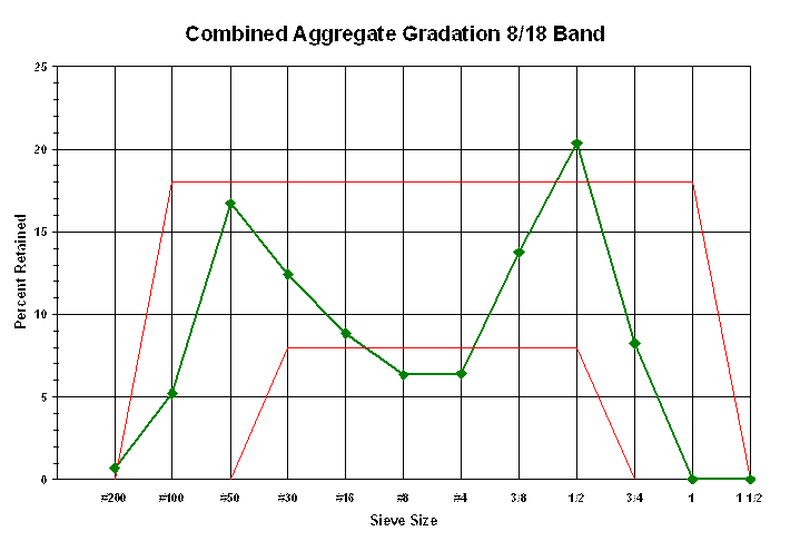
The 0.45 power curve is based on the mathematically combined percent passing gradation determined in accordance with IM 531. Historically, the 0.45 power curve has been used to develop uniform gradations for asphalt mix designs; however, it is increasingly being used to develop uniform gradations for Portland Cement Concrete mix designs.
To create a 0.45 power curve plot the mathematically combined percent passing for each sieve on a chart having percent passing on the y-axis and sieve sizes raised to the 0.45 power on the x-axis. Sieve sizes shall include the 1 1/2 in. (37.5 mm), 1 in. (25.0 mm), 3/4 in. (19.0 mm), 1/2 in. (12.5 mm), 3/8 in. (9.5 mm), No. 4 (4.75 mm), No. 8 (2.36 mm), No 16 (1.18 mm), No. 30 (600 μm), No 50 (300 μm), No. 100 (150 μm), and the No. 200 (75 μm). Connect the plotted points as shown in Figure 2. Plot the maximum density line from the origin of the chart to the sieve one size larger than the first sieve to have 90 percent or less passing.
A well-graded aggregate combination will follow the maximum density line to the No. 16 (1.18 mm) sieve. A slight deviation below the maximum density line at the No. 16 (1.18 mm) sieve will occur to account for the effect of the fines provided by the cementitious materials (Figure 2). A gap graded aggregate combination will produce an “S- shaped” curve deviating above and below the maximum density line (Figure 3).
PERCENT-RETAINED
CHART
The percent-retained chart is based on the mathematically combined percent-retained gradation for each sieve in accordance with IM 531. The percent-retained chart has evolved from efforts to limit disproportionate amounts of material retained on any one sieve.
To create a percent-retained chart plot the mathematically combined percent retained for each sieve on a chart having percent retained on the y-axis and sieve sizes on the x-axis. Sieve sizes shall include the 1 1/2 in. (37.5 mm), 1 in. (25.0 mm), 3/4 in. (19.0 mm), 1/2 in. (12.5 mm), 3/8 in. (9.5 mm), No. 4 (4.75 mm), No. 8 (2.36 mm), No. 16 (1.18 mm), No. 30 (600 μm), No. 50 (300 μm), No. 100 (150 μm), and No. 200 (75 μm). Connect the plotted points and plot the boundary lines as shown in Figure 4.
A well-graded aggregate combination will have no significant peaks and/or dips (Figure 4). A gap graded aggregate combination will have significant peaks and dips (Figure 5). Shilstone recommends that the sum of percent retained on two consecutive sieves should be at least 13% to be an optimum gradation.
OPTIMUM AGGREGATE
BLEND
Determining an optimum combined aggregate blend will require the use of all 3 graphical representations as well as sound practical experience. The coarseness/workability chart should be the primary method used to develop an aggregate combination that will produce a mixture with appropriate properties for the intended application and placement method. The 0.45 power curve and the percent-retained chart should be used as secondary means to verify the coarseness/workability chart results and to identify areas deviating from a well-graded aggregate combination. Aggregate blend for QMC mixes may be found on Form #955QMC (Appendix A).
For BR mixes, a well-graded aggregate mix design on the coarseness/workability chart will plot within Zones II-A and II-B.
AGGREGATE SHAPE
EFFECT ON OPTIMUM GRADATION
The shape and texture of aggregate particles affect the volume of paste needed to coat particles and decrease interactions during placement. The ideal aggregate shape for workability is smooth and round. Smooth and round particles, such as gravels, have a low surface to volume ratio and require less paste to coat the surfaces of each particle. Crushed limestone aggregates, which usually tend to be more angular and rough than gravel aggregates, have a higher surface to volume ratio, and may require more paste to reduce particle interactions.
These rules are generalized and the mix designer must determine the actual optimum gradation, considering particle shape, with placing and finishing characteristics as the ultimate assessment of workability. Although other combinations can be used depending on aggregate top size, shape, and texture, typical optimum aggregate combinations tend to fall within the range of 44-48% coarse, 10-15% intermediate, and 38-42% fine aggregate.
FIGURE 1
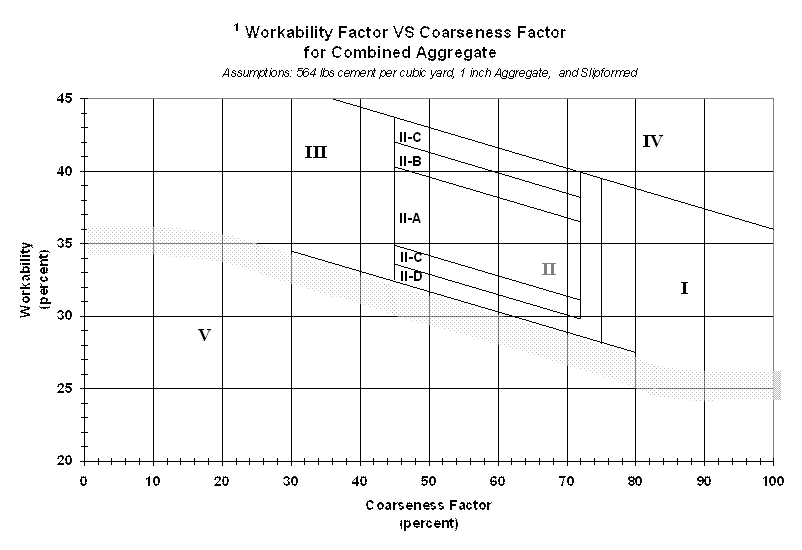
FIGURE #2
|
|
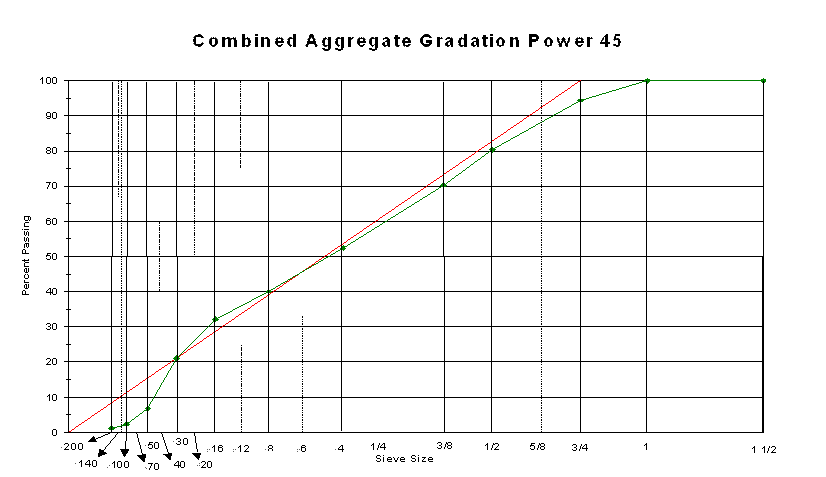
FIGURE 3
|
|
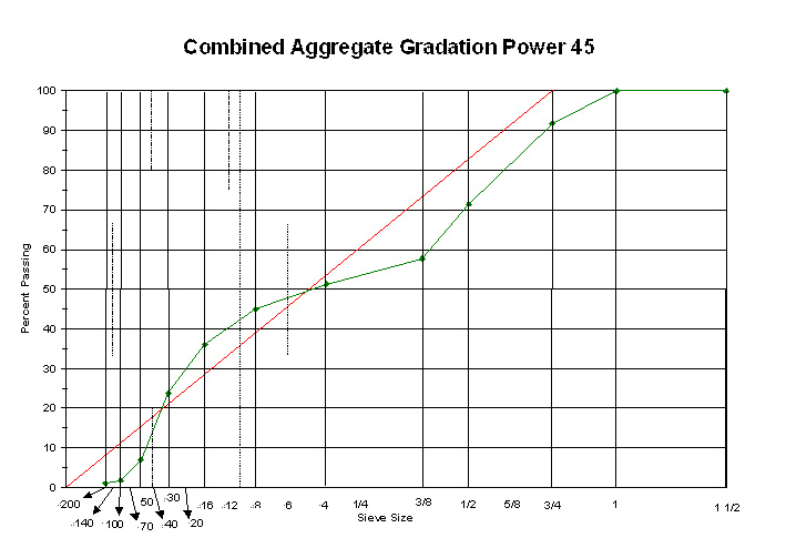
FIGURE 4
|
|
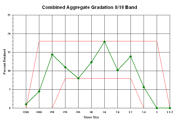
FIGURE 5
|
|