HOT MIX ASPHALT (HMA) PLANT INSPECTION
GENERAL
The Contractor’s Certified, Level I HMA, Technician should witness the contractor operations, from the initial plant set up to the final shutdown. The contractor plant and method of operations should be examined thoroughly before work begins. Any deficiencies, which are observed with regard to specification compliance or safety, should be reported to the contractor and the engineer.
Normally, two certified technicians are required to perform the various materials quality control tests and plant production control inspection functions. The overall responsibility for plant inspection remains with the Contractor. This section deals primarily with this overall responsibility, therefore, no guidelines will be presented regarding division of duties and functions. The assignment of duties and functions of the inspection monitors are the responsibility of the Resident Construction Engineer and the District Materials Engineer.
PLANT INSPECTOR
DUTIES
A. Preliminary
The first phase of the contractor operations consists of preparing the plant site and building stockpiles. The Contractor’s certified technician should be assigned to the project prior to this phase of the work so that those procedures, which are governed by the specifications, may be observed and properly controlled.
The general areas or procedures requiring attention are:
1. Construction of Stockpiles to:
a. Minimize segregation
b. Eliminate contamination and intermingling
This is accomplished by constructing the stockpile in lifts, controlling stockpile height, controlling drifting and rolling of material, constructing partitions or bulkheads, and stabilizing the stockpile work area. Refer to the specifications for specific requirements.
NOTE: All aggregate must be properly certified before being placed in the stockpile.
2. Plant Erection Which Provides:
a. Safe working conditions
b. Reliable operation
This is accomplished by proper site preparation, placement of adequate foundations for bins and mixing equipment and constructing safeguards such as berms and drainage ways.
B. Job Mix Formula (JMF)
The job mix formula together with the specifications provide the initial basis for setting up and starting the job, therefore, the plant inspector must be thoroughly familiar with the information provided by the Job Mix Formula Report (Form #956).
Before the laboratory can develop a job mix formula, the contractor, material producers, and District Materials Engineer must make numerous arrangements in the field. The contractor must first select his/her material sources and estimate, in cooperation with the producers, the tentative proportions and gradations of each of the materials. The District Materials Engineer must be consulted before samples of the materials are obtained. The Contractor is responsible for the mix design per IM 510. Adjustments may be necessary in these proposed proportions since the exact gradations may not be known in advance.
If the composite gradation complies with the limits specified for the job mix formula, production limits are set for the individual aggregates by agreement between the Contractor and the Producer and documented on Form #955.
Aggregate production and inspection are covered in detail by IM 204 and IM 209.
If the materials as first analyzed do not consistently meet the specified limits, it may be necessary to adjust the proportion percentages or production limits. Familiarity with the material sources and production methods facilitates setting realistic limits. This reduces the number of trial and error steps and subsequent adjustments. It is advantageous to maintain records of this type for each material source and type.
When changes are made during the design stage, they will be incorporated in the job mix formula report. If changes are found necessary after production begins, they are to be made as provided for in Materials IM 511 unless a complete new job mix formula is required.
A typical Mix Design Report with a description of information is shown on the following pages.


HMA MIX DESIGN
Refer to:
A JMF aggregate proportions, sources
B JMF target and design gradation with tolerances.
C Source and grade of the asphalt binder used in the job mix formula.
D The target asphalt binder content recommended to start mixture production. Expressed as a percent of asphalt binder, based on the total mass of the mixture. Established during the mixture design process.
C. Sampling and Testing
There are a number of sampling and testing procedures that a plant inspector must be familiar with and perform in order to establish and maintain acceptable quality construction. A number of these tests, measurements, and calculations, in addition to documenting specification compliance, also provide the basis for determining contract pay quantities.
Sampling frequencies are provided for in IM 204 and the Standard Specifications.
Sampling and testing methods are provided for in IM 300 series. IM 511 and the Standard Specifications provide directions on sampling and testing requirements.
D. Plant Equipment
Items of equipment to be checked for specification compliance prior to beginning operations are listed below:
1. Truck Scales or weigh hoppers
2. Cold Aggregate Feeders
3. Dryer
4. Dust Collector and Feeder
5. Cold-Feed Storage Bins and Feeders
6. Revolution Counters, and/or Scales
7. Thermometer Equipment.
8. Equipment for Heating, Storing and Measuring Asphalt Binder
9. Asphalt Pump, Surge Tank, and/or Scales
10. Testing Laboratory
11. Safety Requirements
Refer to the following plant diagrams and descriptions.
BATCH PLANT MATERIAL FLOW DIAGRAM
A. Multiple Compartment Cold-feeder
B. Cold Elevator
C. Drier
D. Horizontal Cyclone Dust Collector & Exhaust Washer
E. Return Hot Aggregate Elevator & Dust
F. Screening Unit
G. Hot Aggregate Storage Bins
H. Aggregate Batcher & Scale
I. Asphalt Transfer Pump
J. Asphalt Batcher & Scale
K. Pugmill Mixer
L. Optional Mineral Filler Elevator
M. Optional Mineral Filler Feeder
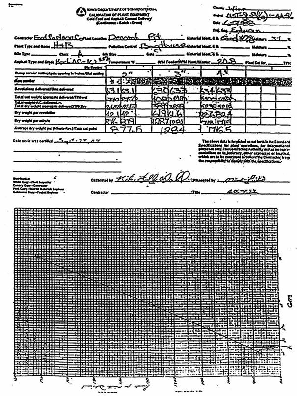
E. Plant Calibration
The specifications require that all material proportioning equipment be calibrated and checked for accuracy. The job mix formula provides the basis for the calibrations.
The specifications require the contractor to provide personnel, scales, test weights, and equipment for calibrating each delivery component. The plant inspector shall determine moisture contents of the various materials. Use the formula:
![]()
The plant calibration may be monitored by and is subject to the approval of the District Materials Engineer or authorized representative. The plant inspector should be present and observe all procedures. The Contractor will furnish the plant inspector with copies of the calibration results, so adequate information is available for making adjustments when indicated. Should difficulty be experienced during plant calibrations, the District Materials Engineer should be contacted for assistance. Normally, the District Materials Engineer will assign one or more experienced inspectors to monitor the calibration of proportioning and mixing plants. The plant inspector should be thoroughly acquainted with plant operations, so problems are recognized and corrected as early as possible.
A sample calibration has been included as a guide in this section. Due to the wide variation in plant equipment, this example will not cover all situations, but it should provide the basis for understanding the overall procedure.
1. Cold Aggregate Feeders
The first step in calibrating a proportioning plant is the calibration of the cold aggregate feeders. These units determine the final gradation of the mixture.
a. Fixed Speed-Variable Gate Opening Cold-feeders
These feeders are controlled by gates, which meter the flow volumetrically. They are calibrated by weighing the quantity of material, which passes through a given gate opening during a measured time interval. The interval is determined by counting the number of revolutions that the feeder makes while the material is delivered. From the RPM of the feeder and the weight (mass) of the material, the deliver rate in pounds (kg) per minute is calculated (corrected for moisture). The calibration is graphed by plotting the pounds (kg) of dry aggregate delivered per minute at the gate openings used in the calibration.
b. Fixed Gate Opening-Variable Speed Cold-feeders
With this system, a gate opening is selected for each cold-feeder. This gate opening must be maintained throughout the calibration and the job. They are calibrated by weighing the amount of material delivered at several different speeds of the cold-feeder motor over a measured time interval.
The calibration is graphed by plotting the pounds (kg) of dry aggregate delivered per minute at the speeds of the cold-feeder motor used in the calibration.
These cold-feeders are equipped with a master control, which may be used to adjust the production rate. Changing the master control setting changes the speed of all the cold-feeders proportionately.
c. With either type of cold-feed, the gate setting is very important and should be checked regularly.
d. Refer to the example calibration forms included.
2. Conveyor Scales
The specifications require Drier Drum Mixing Plants be equipped with continuous weighing central conveyor scales that are interlocked with the asphalt deliver system. These scales are checked for accuracy by two methods as follows:
a. The scale is first zeroed while the conveyor is operating at normal operating speed, but unloaded. It is then adjusted to readout a predetermined total weight (mass) using the special scale beam weights and a standard operating time interval. Both of the foregoing procedures are to be performed in accordance with the scale manufacturer's instructions.
b. The second accuracy check requires the comparison of the weight (mass) shown on the totalizing meter, with the weight (mass) actually delivered as determined by running material over the conveyor into a tared truck. The truck tare and loaded weights must be obtained by weighings over certified commercial truck scales, or plant scales that have been checked against certified scales and approved by the Engineer. The conveyor scales should be checked at several delivery rates representing the proposed operating range. The contractor shall adjust the weighing system so that when the plant is operating, the final mixture is uniform and consistently within the specified job mix formula tolerances.
3. Asphalt Pump
Some batch plants, all continuous and drum mixing plants deliver asphalt material to the mixer through volumetric pumps. The pumps are adjusted by changing drive sprockets or movement of a vernier dial control. These volumetric systems must be calibrated throughout the proposed operating range at the normal operating temperature. When totalizing meters are required, they must be adjusted to readout the quantity delivered within the specified deliver tolerance.
If the contractor elects to use in-line flow meter readings for pay, the meter must be accurate to plus or minus 0.2% as demonstrated through the calibrations process or by comparison to tank stick readings if approved by the DME. If this degree of accuracy cannot be attained, measurement for pay shall still be by tank stick. Unless otherwise approved by the DME, use a certified truck scale in the calibration of flow meters.
When a flow meter is used for pay, yield checks will be performed.
4. Hot Aggregate Feeders on Batch Plants
After the various aggregates have been proportioned and dried, they are fed to the mixer unit.
a. On batch plants the hot aggregates are weighed in batches over calibrated scales as described in the following paragraphs and examples.
The dust collected by the dust collector is fed from a calibrated bin or returned directly to the hot aggregate, depending on the type of plant equipment and the specification requirements. If the dust is returned separately, the feeder should be calibrated to feed the required quantity of dust in a uniform manner. If the dust is returned directly to the hot aggregate the weight or volume of dust collected and returned is taken into account automatically in the calibration of the hot aggregate delivery system or batch weights.
When gradation control is by cold-feed samples, and the batch plant is equipped with hot aggregate screening units, they should be removed or covered so that the gradation is not altered by the balance of the hot bin delivery settings. If the Contractor would like to use the hot aggregate screening process, the approval of the DME is required before beginning. If this process is used, the gradation control will be based on samples obtained from the hot aggregate delivery or on the extracted gradation from samples of the hot mix. When hot aggregate screening is used, the delivery of each hot bin must be calibrated similarly to the cold feed bins.
5. Batch Plant Scales
Calibration of batch plant scales as required by the specifications is performed by incrementally loading the scales with standard test weights and partial batches through the operating range of the scales. As each increment of load is applied, the actual observed weight and the required weight are compared. The differences, plus or minus, are determined and converted to percentages of the required weight. If the percentage deviations are less than the tolerance allowed by the specifications and the scales are sensitive to the test loads, the scales will be considered in calibration. If the scales do not meet the various requirements, the contractor is required to make the necessary repairs or adjustments. Recalibration may be ordered by the engineer if the scale equipment malfunctions or if required material quantities do not agree with actual material quantities. If the batch plant scales are to be used for the determination of pay quantity, a scale calibration to the proper accuracy is required.
6. Initial Plant Settings
Three examples of initial plant settings have been provided: one for a drum mix plant, one for a 3000-pound (1,361-kg) batch plant with a volumetric asphalt measurement, and one for a continuous plant with a sprocket type asphalt pump.
The plant inspector is at this point cautioned not to make adjustments or effect settings of plant equipment, and in no way manipulate or operate any equipment at any time. All operations connected with the contractor plant or other equipment are by specification the strict and total responsibility of the contractor.
7. Mixing Rate
The specifications contain requirements regarding the quality and duration of mixing for the various types of mixes and plants. The design, condition, speed and loading of the mixer unit together with the characteristics of the materials being mixed will vary from job to job and need to be taken into account when evaluations are made.
Mixing times are determined in the following manner:
b. Batch Plants. The mixing rate of batch plants is controlled by the batch size and the dry and wet mixing timer settings. The batch size should not exceed the manufacturers rated capacity and the timer should be set to provide the specified mixing time unless more or less time is authorized by the engineer. The accuracy of the timer may be checked with a stopwatch if necessary.
INITIAL PLANT SETTING
TYPICAL PLANT
COLD-FEED SETTINGS
The following example is based on initial plant output of 70 TPH (63,500 kg/hr) of mix. See example.
Set for 70 TPH (63,500 kg/hr.) total cold-feed aggregate (Dry Weight):
![]()
![]()
Material % in Mix kg/min. (lbs./min.) Gate Setting
1/2 in. (12.5 mm) Cr. Stone 60% 35 1400 Approx. 3 5/8
Sand 40% 423 933 Approx. 2 1/8
DRUM MIXING PLANT
The following example is based on initial plant output of 300 TPH (272,160 kg/hr.). See example.
Set aggregate delivery controls on plant control console to deliver 300 TPH (272,160 kg/hr.) of dry aggregate.
Master control set on maximum.
kg/hr or TPH kg/hr or TPH
272,160 or (300) x 58% 3/4 inch crushed limestone = 157,853 174
272,160 or (300) x 30% Sand = 81,648 90
272,160 or (300) x 12% RAP = 32,659 36
100% 272,160 300
BATCH PLANT SETTINGS
After the aggregate scale and asphalt scale has been checked for accuracy, the batch weights are set and mixing operations are begun. The scales are checked by adding weights to the hopper and observing the scale dial indicators (see examples). Some batch plants are equipped with volumetric asphalt pumps rather than scale buckets; these devices are calibrated the same way that asphalt pumps are calibrated on drum-mix plants, but operated on a batch basis:
Assume 3000 lb. (1,361 kg) batch plant, cold-feeds as cited previously and 5.5% binder content.
SCALE SETTING
Binder: 5.5% x 3000 lbs. (1,361 kg) = 165 lbs. (75 kg) per batch (see example)
Combined Hot Aggr: 3000 lbs. (1,361 kg) – 165 lbs. (75 kg) = 2835 lbs. (1,287 kg) per batch
Asphalt pump (volumetric) = 165 lbs. (75 kg) per batch = 23 counts per batch (see example)
If the dust is returned directly to the hot aggregate, separate computations are not required for the dust being fed since it is automatically included in the hot aggregate delivery.
All gate and scale settings and weighing controls shall be set to target on the required quantities. Offsetting shall not be permitted, except to correct calibration errors.
F. Production Inspection Duties
1. Temperature Control
It is necessary to observe and control the temperature of the various material components to document specification compliance, to prevent damage to the material, and to produce uniform workable mixtures. The specifications contain the ranges and tolerances for each type and class of mixture. The specification limits for mix temperature are the same for all plant types. Production above or below these limits must be approved in advance by the Engineer, and documented as set out in Section 1108.04 of the Standard Specifications.
Point of Test (Temperature)
· Asphalt Binder Delivery units and storage tanks
· Aggregate Dryer Pyrometer
· Final Mixture Point of Discharge from mixer (May be obtained from the internal instrumentation providing real-time information to the control house)
· Final Mixture (on road) Behind Paver
2. Gradation Control
a. Cold-feed Gradation Control
The contractor is responsible for ensuring the gradation of the final mixture consistently complies with the requirements of the job mix formula. Cold-feed proportioning will be monitored and verified as part of the overall plant inspection activity. The final acceptance gradation will normally be based on the cold-feed gradation.
Advisory sampling and testing will be performed at the aggregate sources and after cold-feed combination at the plant site. Cold-feed check samples will be taken daily to verify the accuracy of proportioning and to provide guidance to the contractor with regard to mixture gradation. Addition quality tests above the minimum specified may be run at the option of the District Materials Engineer.
The sampling and testing frequencies are outlined in Materials. IM204. Samples must be secured in a safe and reliable manner as provided In Sections 1108 and 2001 of the Standard Specifications. Testing procedures shall be in accordance with IM Series 300.
The cold-feed samples are to be obtained by incrementally cutting the stream or belt flow of combined aggregate feeding the drier. The contractor is responsible for furnishing a plant set-up that allows representative samples to be obtained. This may require equipment modification.
b. Non-compliant cold-feed gradation and other production mix irregularities may result from the following causes:
· Sample not representative of lot (Multiple hot bins)
· Improper bin balance
· Test errors, weights, calculations, etc.
· Incorrect cold-feed settings
· Non-uniform cold-feed delivery
· Stockpile segregation
· Stockpile contamination
· Storage bin segregation
· Intermingling of aggregates in stockpiles and/or feeders
· Wet, non-uniform stockpiles
· Degradation
When the sieve analysis test indicates the combined material does not comply with the gradation requirements, the plant inspector shall take the following steps:
1. Recheck test procedures and computations.
2. Check gate settings and feeder operations.
3. Check the materials and material handling procedures.
4. Notify the RCE, the DME and the contractor of the results.
5. Obtain a second sample and test promptly.
If the gradation tests and/or inspection observations indicate that proportioning irregularities are occurring, the contractor is required to take corrective action immediately. Adjustments in proportions and other job mix formula changes must be documented in writing, in accordance with IM 511.
Several alternatives are normally available to the contractor when difficulties are encountered:
· Change material handling procedures.
· Correct proportioning.
· Change proportions. (Job Mix Formula irregularities change.)
· Waste fines collected by dust.
· Change materials. (New Job Mix Formula collection systems required.)
· Reset Job Mix Formula target.
· Change processing procedures at gradation source.
3. Asphalt Content Control (Also refer to Materials IM 509.)
The control of this material component is the most important plant inspection responsibility because the performance of the finished pavement is directly related to the quantity of binder incorporated in the mix. Separate check systems are used for drum-mix and batch plants as follows:
a. Drum Mixing Type Plants
During the first day or two of operations, and during periods when asphalt or aggregate delivery is questionable, it is advisable to perform proportioning validation in addition to the measurements required in IM 204. The specifications require drum-mixing plants to be equipped with totalizing asphalt meters and aggregate scales.
This equipment and information should be utilized for making continuous checks. Total asphalt delivered as indicated by the meter should be periodically compared with quantities used as determined by tank measurements.
Validation Methods:
(1) Compare asphalt delivered by metering pump or scale with outage shown by 2 or 4 hour tank measurement (compare by pounds (kg), gallons (liters), or percent).
(2) Compare total mix produced, including waste, to asphalt and aggregate delivered by plant for a given period of time.
b. Batch Type Plants
The operation of batch type plants should also be verified when work begins on a project. This is done by making intermediate tank measurements at 2-or 4-hour intervals and by checking the operation and sensitivity of the scale equipment.
If the measurements indicate that uniform control is not being maintained, the contractor is required by the specifications to adjust and correct his operations to obtain specification compliance. Such actions may include but not be limited to cleaning, repair, or replacement of equipment, recalibration of pumps and feeders, and training of personnel. In some cases it may be necessary for the contractor to obtain assistance from equipment manufacturers or distributors. Refer to the checklist on pages for possible causes of difficulty.
The inspectors should be aware of the fact that the specifications provide for establishing mutual agreements for determining asphalt quantities on projects involving small quantities, or intermittent or diversified operations.
c. Plant Inspection Control List
1. Before Calibration
a. Check capacity of storage tanks.
b. Check tank sticks.
i. Be sure they fit the tanks.
ii. Determine proper use. (touch stick or dipstick, percent of diameter or inches, etc.)
iii. Be sure tanks are level.
c. Check piping and type of pumping system.
d. Learn the contractor method of operating the system.
e. Check the truck scales.
2. During Operation
a. Determine percent binder by tank stick measurement method as required.
b. Determine percent binder by verification as required.
c. Check batch scales for sensitivity.
d. Check truck scales for sensitivity and accuracy.
3. If Computed Percent Binder is High:
a. Check tank stick readings and computations.
b. Check to be sure that all mix produced was included in the computations.
c. Check for spilled, wasted, or otherwise used asphalt cement.
d. Check to be sure all asphalt listed as added during the period should be included.
e. Check truck scales and total mix made.
f. Check cold-feed and pump setting.
g. Check aggregate delivery level for uniformity.
4. If Computed Percent Binder is Low:
a. Check tank stick readings and computations.
b. Check total mix made.
c. Check to be sure that all asphalt added during the period is included.
d. Check cold-feed and pump setting.
e. Check for plugged nozzle.
f. Check pumping pressures.
g. Check strainer screen.
h. Check truck scales.
IM 509 provides the detail procedure for making tank measurements and determining asphalt content.
G. Checking Scales
1. Batch Scales
Batch scale sensitivity shall be checked once per day during a normal working day by placing a weight equal to 1/10 percent of the batch weight but not greater than 20 lbs. on the fully loaded scales and observing the movement of the indicator. A properly sensitive scale will exhibit a visible indicator movement when so tested. If no indicator movement is visible, immediate corrective action must be taken by the contractor.
The specified scale delivery tolerance limits should be checked by periodically witnessing the batch weighing operations. Each scale indicator should consistently indicate the required weight within the specified delivery tolerance, and return to zero when unloaded within the specified 0.5 percent tolerance.
When automatic batch weighing equipment is used, the interlock system shall be set at the 1.0 percent limit as specified. They may be manually overridden to continue plant operation if the specified delivery tolerance is not exceeded. When the delivery tolerances are exceeded, the asphalt or aggregate batch sizes shall be adjusted manually to bring the batch into compliance, or it shall be wasted.
The plant superintendent or other authorized contractor representative must make all necessary scale and equipment settings and/or adjustments. Before the plant operation begins or resumes the plant inspector will independently determine for himself that the settings and/or adjustments are accurate and that the weights of material being delivered to the batch are correct.
Normal plant operation causes vibration, which tends to change these adjustments. Accumulation of material clinging to the inside of the weighing hopper can also cause these adjustments to drift. If the amount exceeds one percent of the material batch weight it must be removed and the empty weight readjusted to indicate a zero load.
2. Truck Scales
Truck scales shall be checked as provided in Standard Specification 2001.07.
H. Specification Compliance
All materials shall be inspected prior to being incorporated in a pavement structure. Some materials are being shipped to projects under certification programs and others must have a report. In either case it is necessary to check and file the reports or certifications such that each final product component is properly identified and incorporated with the proper documentation. This is accomplished by obtaining the documents for each lot of material before incorporation. All shipments of all materials incorporated shall be logged as they are received.
A Non-compliance Notice (Form #225) shall be immediately delivered to the acting representative of the contractor for the area of construction involved whenever procedures or tests results on acceptance samples representing material to be incorporated or incorporated in the work indicate non-compliance with the specifications and plans. Appropriate action in accordance with the applicable specifications and Instructional Memorandums shall be taken.
I. Sampling and Testing
The Contractor’s Laboratory Technician is responsible for meeting all sampling, testing, and documentation requirements as set forth by Specification 2303 and IM 511.
NOTE: RAP gradation % passing is found on Form #955.
J. Completed Project
When a project is completed, the plant inspector should again check all records and documentation for accuracy and completeness. It is also necessary to determine at this time the net quantity of materials incorporated in the project. The field records and plant records should be compared and final determinations made.
K. Diary and Report Requirements
1. The diary must be filled out daily.
2. Computer programs are provided to document what is required.
Daily Plant Report. This form is submitted daily to document plant operations, job control testing, and material placement on all hot mix and cold mix construction.
Identification of Sample for Test (Form #193). This form must accompany all samples submitted to the Central Laboratory and District Laboratories. Examples of completed forms have been included in this instruction.
3. Testing Worksheets. All worksheets and other original documents used by inspection personnel are to include identification of: 1. individuals associated with sampling and testing, 2. County and Project No., 3. Material and sampling point, 4. Date and time of sampling and testing and, 5. Source, producer or contractor. All documents other than field notebooks are to be filed with the appropriate report and retained per the file retention schedule.
L. Mixture Segregation
In addition to determining if all of the required equipment is available, calibrated, and functioning properly, the plant inspector should monitor mixture uniformity for potential problems. One of the most troublesome difficulties encountered during production is mixture segregation, which may be caused by plant equipment or operation. Segregation at the plant may be caused by:
1. Pugmill discharge being too high above the truck bodies.
2. Depositing into very large truck bodies, causing the mixture to cone and roll. In this case trucks should be moved back and forth during loading.
3. Pugmill or storage gates opening improperly. They may not open or close quickly or to the full extent of the opening.
4. Inadequate mixing. This may be caused by short mixing cycle, improper mixer paddle positioning, worn paddles, or low level in the mixing chamber.
5. Improperly designed, maintained, and operated surge and storage bins and conveyors. Example - material discharge into conveyor must be centered into the bucket or belt.
6. Failure to provide near level truck charging platform.
Coarse, lean mixtures are more subject to segregation than fine-rich mixtures; therefore more care must be exercised when coarse mixtures are being produced. Segregation of the mix results in non-uniform distribution of the material in the pavement. This can lead to a patchy appearance as well as early structural distress.
M. Asphalt Binder Contamination
Another potential problem encountered during production is contamination of the asphalt binder. This may be caused by:
1. Allowing fuel oil used for cleaning pumps and lines to enter the storage tanks.
2. Accepting delivery of non-specification material or material of a different grade.
3. Leakage of plant heating oil into the storage tanks.
4. Contaminated delivery tanks.
5. Improper sampling, and sample catching container, refer to IM 323.
Alert inspection and proper supervision can prevent contamination by the contractor since most of the problems are associated with the use of cleaning fluids and improper material combination.