FLEXURAL STRENGTH OF CONCRETE
SCOPE
This test method is used for determining the flexural strength of concrete by the use of a simple beam with center-point loading.
PROCEDURE
A. Apparatus
1. Hydraulic testing machines provided on Portland Cement Concrete paving projects shall conform to AASHTO T-177. The hydraulic machine consists of a frame to hold the specimen, a hand-operated hydraulic jack, and a pressure gauge to read the load. Practically all of the hydraulic machines have a micro pump in the loading line to facilitate control of the last half of the load within specifications, and without pause in loading. A calibration sheet is included with each machine of this type. Additional equipment needed includes a caliper, plastic ruler and a tri-square. The hydraulic test machine needs to be calibrated annually by the DOT Central Laboratory. Calibration sheets with each machine will indicate the date last calibrated.
B. Test Specimen
1. The test specimen shall have approximate dimensions of 6 in. x 6 in. x 20 in. (152 mm x 152 mm x 508 mm). The test specimen shall be kept wet until the time of the test.
C. Test Procedure
1. Either before or after the beam is placed in the testing machine, draw a reference line on the top and bottom of the beam, as cast, about 10 in. (250 mm), or centered, from the end of the specimen. The two reference lines should be exactly opposite each other. A line drawn across the bottom of the beam, as placed in the machine, will meet these two lines, and will be perpendicular to them. The bottom of the beam as placed in the machine will be the side of the beam as cast.
2. Insert the stirrup pins in the slots at the bottom of the stirrups to prevent the stirrups from swinging while the beam is being placed in the machine. This also assures that the support bearings are in the correct position.
3. Place the beam in the testing machine so that the two reference lines on the side of the beam are directly under the centerline of the center bearing. The maximum fiber stress during application of the load will occur in the outer fiber in the line drawn across the bottom of the beam, this line being directly under the load.
4. Rotate the micro pump handle counter-clockwise to expose the maximum number of threads, and close the loading valve on the pump.
5. Apply a small initial load, and remove the stirrup pins.
6. The load may be applied rapidly up to approximately 50 percent of the estimated breaking load with the pump handle. The final half of the loading is accomplished by turning the crank of the micro pump, at a rate that the extreme fiber stress does not exceed 150 psi (1.0 MPa) per minute. This is approximately 1200 pounds (500 kg) per minute on the test gauge.
7. Using one of the fractured faces, take one measurement at each edge and one at the center of the cross section for each direction (width and depth). Make measurements to the nearest 0.05 in. (1 mm). Average the three readings to determine the average width and average depth of the specimen at the section of failure. (Figure 1)
8. Measure the distance from the line drawn at the center of the span to the location of the break on the bottom side of the beam as tested. If this distance exceeds 1 1/2 in. (40 mm), the test results will not be used in determining when a pavement can be opened to traffic, when forms may be removed from a structure, or when a concrete structure can be subjected to exterior loads, which produce flexure.
D. Calculations
1. From the calibration sheet furnished with each machine, determine the corrected load placed upon the beam. The machine should be calibrated annually.
2. Calculate the modulus of rupture as follows:
![]()
Where:
R = Modulus of rupture, MPa or psi.
P = Corrected load indicated, N or lb.
I = Span length, mm or in., between supports (or 18 in. or 457 mm)
b = Width of beam at point of fracture, mm or in.
d = Depth of beam at point of fracture, mm or in.
3. The typical range of modulus of rupture should be from 300 psi to 700 psi (2 MPa to 5 MPa). Report the modulus of rupture to the nearest 5 psi (0.05 MPa).
E. The following figure shows the beam as it should be placed in the flexural testing machine, with the finished top as casted turned on its side.
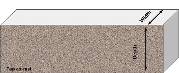
Figure 1
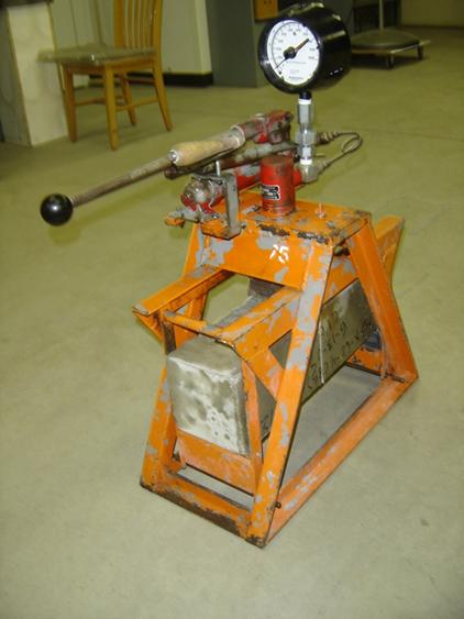
Figure 2. Concrete Specimen in Hydraulic Testing Machine
F. Precautions
Always make sure the pointers on the gauge are set at zero before any loading begins.